|
|
In response to several requests for more information on the plenum design
I would offer the following:
Gary asks:
<<
It looks like the cross-section area increases as you go
back from the front of the engine - wouldn't you really like to have the
area decrease from the first row of cylinders to the last?>>
No, for two reasons. One, since the airflow is limited by the engine and
coolers and not the inlets, you want the plenum to have as large a volume
as possible to slow the air as much as possible and to recover as mush pressure
as possible. It is the pressure, not the velocity, that drives the cooling
air through the engine. Two, all the coolers are at the back of the engine.
I have been very satisfied with the cooler arrangement. There is a school
of thought that says the coolers need to be up in the front where the air
is coldest. Unfortunately the air is also at it's lowest pressure there so
there is little reason for it to go through the cooler. Remember that the
lower plenum (the part after the engine but before the discharges) is at
a higher pressure than the free stream. It wouldn't want to leave if it wasn't.
Therefore with a front mounted cooler the free stream static pressure is
LOWER than the lower plenum pressure so the static pressure is working against
the kinematic pressure. Kinematic pressure is recovered in the fins of the
cooler and since there is no diffusion this is not an efficient process.
Read poor cooling and lots of drag.
FOD is also a problem for front mounted coolers. I had originally anticipated
needing to add secondary internal ducts to bring cold air back to the coolers
but flight testing demonstrated that this was clearly unnecessary.
<< Also, why connect the two sides of the plenum since there is nothing
in the middle to
be cooled? Simplicity of construction, I assume?>
You are correct, sir! Simplicity and more volume were the motives.
<< where did the engine mount come from?>>
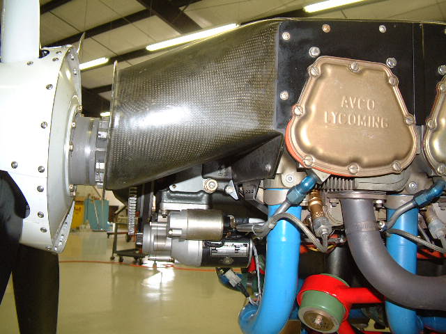
Old "bean hole" alloy wheels. Actually I am serious about this one. When
I first took on the challenge of adapting the Lycoming I started with designing
a new engine mount. The problem was that while a dynafocal mount is more
efficient in carrying flight loads, the bed mount is more efficient in carrying
landing and ground loads. The location of the nose gear dictated that a bed
mount engine mount will be substantially lighter and simpler that a dynafocal
mount. The difference is close to 14 pounds! Not acceptable! The alternative
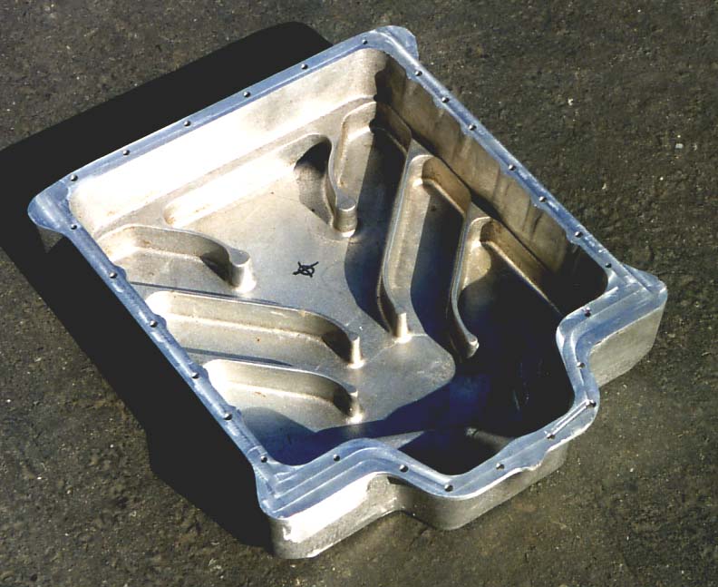
was to redesign the engine sump to convert the Lycoming engine to bed mount.
I bought a surplus milling machine frame and converted it to CNC. Using this
I made a casting pattern for the new sump from high density (30 lbs/cuft)
urethane foam and sent it to a specialty foundry in LA. The foundry uses
A356 aluminum alloy and the best source for short runs of this allow are
scrap alloy wheels. The result is pictured below. I built 7 other sets of
hardware and sold them to amortize the cost of this effort and then sold
the tooling to Lycon in Visalia. 6 of the original 8 are currently flying,
one is building and one was destroyed in a icing induced crash.
Larry writes:
<< I would appreciate your taking the time to explain how you built
such a high quality cooler.>>
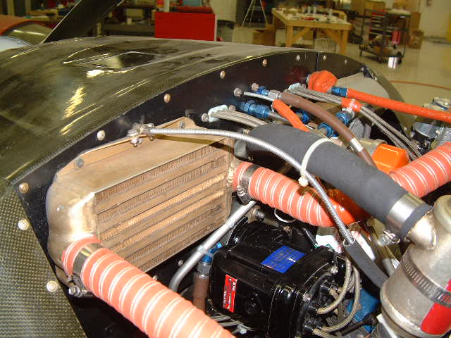
The intercooler and inlet ducts were made by forming a 3 bid layup (Jeffco
epoxy) on high density urethane molds that I hand sculpted and sealed with
automotive paste wax. For the front inlets I had to split the layups to get
them off the mold. I glued them back together and then layered them inside
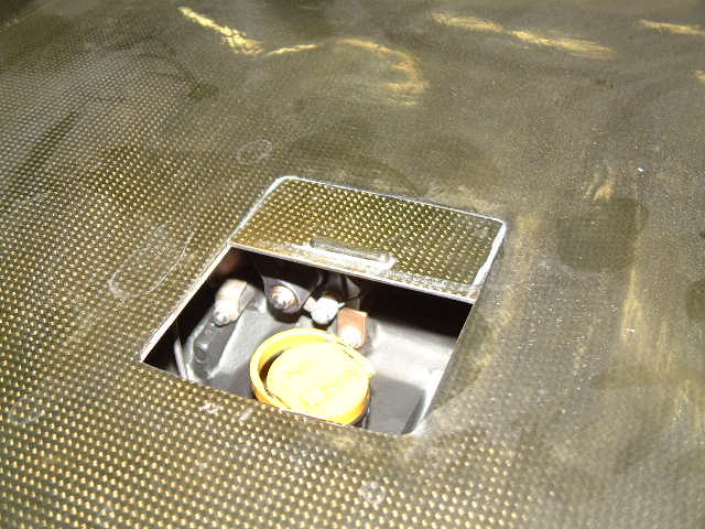
and out with 1 bid of carbon. The cover was formed from the inside of the
cowling. I used aluminum sheet and urethane foam to form the flanges and
flat area for the oil door and then covered everything in packing tape. Again
three bid E-glass was used. The E-glass was sanded before the "finish" coat
of carbon was applied. Foam stiffeners were applied and covered with two
bid carbon where needed. All parts received a soaking of West epoxy for cosmetics
and oil sealing.
A photo and sketch of the oil door are also attached.
The resulting engine installation has an all up wet weight of 609 pounds.
This includes all accessories, plumbing, controllers, vibration mounts, baffling,
coolers (4 each), standby alternator, oil, transducers, prop governor and
all ducting. Weight savings in the engine installation were a major factor
in keeping N170BR's empty weight to 2188 pounds.
Regards
Brent Regan
Sump.jpg
N170BR-3.JPG
N170BR-4.JPG
N170BR-oil.JPG
|
|