Since this thread has not come to a correct or
satisfactory conclusion, but merely continued some incorrect views without
objection, I hereby object!
(Harrumph!)
Rather than write an article and wade into the fray
with my own poorly written descriptions and pictures, I refer those who want
the final word to
http://www.grc.nasa.gov/WWW/K-12/airplane/lift1.html
Short summary: Lift
occurs because flow is turned downward creating downwash.
The web site also discusses several of the wrong
theories and explains why they are wrong.
See among the pages available:
http://www.grc.nasa.gov/WWW/K-12/airplane/right2.html
Excerpt (red highlights added):
HOW IS LIFT GENERATED?
There
are many explanations for the generation of
lift found in encyclopedias, in basic physics textbooks, and on Web sites. Unfortunately, many of the explanations are misleading and incorrect. Theories on
the generation of lift have become a source of great controversy and a topic
for heated arguments.
To help you understand lift and its
origins, a series of pages will describe the various theories and how some of
the popular theories fail.
Lift
occurs when a moving flow of gas is turned by a
solid object. The
flow is turned in one direction, and the lift is generated in the opposite
direction, according to Newton's Third
Law of action and reaction. Because air is a gas and the
molecules are free to move about, any solid surface can
deflect a flow. For an aircraft wing, both the
upper and lower surfaces contribute to the flow turning. Neglecting the upper
surface's part in turning the flow leads to an incorrect theory
of lift.
Wander around the web site a bit, and be
patient. There is a lot to learn.
Be sure to see:
http://www.grc.nasa.gov/WWW/K-12/airplane/bernnew.html
for the Newton vs. Bernoulli arguments. Hint:
both are right. It depends on your perspective.
Since I like moving pictures, have a look at the moving
visual presentation down the page a bit at
http://www.grc.nasa.gov/WWW/K-12/airplane/wrong3.html
which shows the flow field around a wing at different
angles of attack. Change the angle of attack. Move the probe around
with the slider bars to see how pressure and velocity change around the wing,
particularly close to the leading edge. Also note the amount of up flow
in front of the wing, particularly at higher angles of attack. The flow
moves up because the pressure above and in front of the wing the wing is lower
than below and in front of the wing. The low pressure field extends in
front of the wing leading edge (subsonic flow, not supersonic flow). See
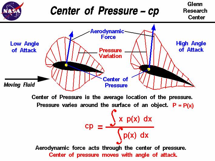
pressure diagrams around wings below. Pressures above the wing are low (“suction”
compared to the free stream ambient static pressure) as are pressures below the
wing, but the low pressure times area on the top is higher than the low
pressure times area on the bottom, and thus the net force is up – lift.
Putting reflex shape and other shapes on the wing profile changes the pressure
distribution, but the net effect is still the same – pressure difference
between top and bottom yield lift. The difference in pressure forces
deflects the flow. Action and reaction. Note also that if the
inside of your landing gear bays are pressurized with air leaking in from some
higher pressure area, the pressure around the outside of the landing gear door
will be lower, and doors will be pushed open as previously discussed. This
is particularly true for nose landing gear doors which are pressurized with
cowl air, but I digress, as usual.
Fred
“With all thy getting, get thee understanding.” -
Malcolm Forbes.