[ photos re-compressed -Rob ]
-------- Original Message --------
Baffling solved?
<<baffling 003.JPG>> <<baffling
004.JPG>> <<baffling 009.JPG>> <<baffling
010.JPG>> <<baffling 013.JPG>> <<baffling
014.JPG>>
I
listened with great interest to the
baffling questions, saw the posts, read Walter’s
responses, understood what
was taught at the Advanced Pilot’s
Seminar, looked at the current baffling in my engine,
drew some conclusions and tried some changes. I
am greatly appreciative of all the discussion and participants.
Disclaimers: I am not an engineer, have no
vested interested in anything but my Lancair and have not bones to
pick.
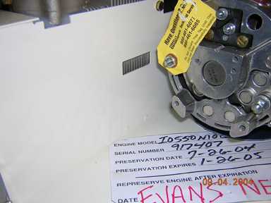
I have a
TCM TSIO 550 E with Lancair firewall forward kit from late 2000 on
a IVP with 620 hours.
I had
already upped my fuel flows at WOT to 43 gph. I
also see 32 gph at 2500 rpm and 31”
MP. (This is a critical part of keeping the engine cool as the TCM
settings are most likely too low of fuel flows to keep the engine cool. I
learned this from George Braly.)
Problem:
Number 2 and 5 run hotter. Can’t
climb at full power more than a 4-5 minutes before the head
temperatures start climbing excessively,
esp. #5.
Problem:
The barrels come
to the edge of
the cooling
fins on all cylinders at the biggest finned area
about 2” wide..
This is a problem on number 2
and 5 where the baffling is tight against cylinders
blocking airflow over the 2”.
Solution:
Get more air around the front side of #5 and the rear side of #2.
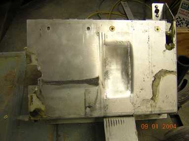
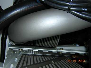
Picture
003 and 004 shows the swaging of the
baffling of #2 cylinder. 003 is the cylinder side
and 004 is the inside of the oil plenum. I did not want to cut a
hole and violate the plenum for the oil cooler. If I had
cut a hole as seen on an earlier post I had no clue what this
would have done to the airflow or my ability to control the
oil temp. The swaged area is 2.125”
wide and 3.5” tall and ¼” in
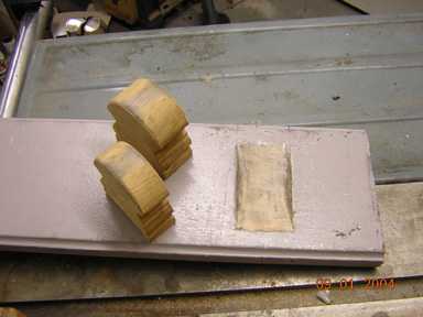
depth at the center. Picture 009 is
the pattern used in creating the cavity to
shape in a board. I
pounded the aluminum with curved oak piece of hand railing. Note
also that I beveled the walls and clamped the baffle to the board
with angle iron.
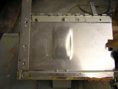
Picture 010
shows the hole I cut in the front baffle of #5.
The hole shown is 1” x
2.125” and is too big. I
subsequently covered ½
the hole so it is now ½” by
2.125”. This seems to be about right, perhaps
still a little cooler than it needs to be.
If you are wondering how I cut this, I did not remove the baffle or
the alternator. I used a dental high speed handpiece with a fluted
carbide burr.
(Nice to have a dentist/son in
the family.) About 10 minutes to make
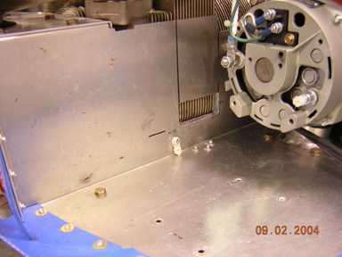
this mod. Picture 013 Now
look at what Lancair has done on their production baffling for the last
8 months. Their hole on #5 is
higher than mine. The top of
the hole is just at the point where the barrel of the
cylinder closes off the air from the cooling fins. I like their
solution better. Picture 014 They have
also moved the oil plenum
behind #2 rearward about ¼” and modified
the other attached baffling to
reposition it back to the cylinders.
I suspect that this is a very good solution also. Maybe someone on the
list flying with these mods can share how these work.
Results:
I can now climb full power to 13,500 with the highest CHT at 340
degrees. 150-155kts IAS, 1800-2000fpm
(This is as high as I have climbed since the mods last week.) I
will test this to FL 240 in
a trip later this week. In cruise at
8500’ 32”MP,
2470 rpm, 17.2 gph, OAT 10C, TIT 1522
EGT/CHT
1 1578/316
2 1540/296
3 1560/288
4 1512/288
5 1540/275
6 1446/296
Carl Cadwell
Cadwell Laboratories, Inc.
909 North Kellogg Street
Kennewick, WA 99336
1 800 245 3001
509 735 6481
Fax: 509 783 6403
Email: carlc@cadwell.com
www.cadwell.com
www.quickmed.com
baffling 003.JPG
baffling 004.JPG
baffling 009.JPG
baffling 010.JPG
baffling 013.JPG
baffling 014.JPG
|