|
|
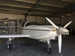
Can anyone comment in regard to sloping the inlet?As in the P51 dog box intake and how from memory most models were canted back at the lower edge. Was this to increase effectiveness in a climb attitude? But if so, what did this do in level flight? This thread has me wondering about adjusting the oil inlet on our Glasair (below the spinner). My Dad turned up a piece of foam that was then glassed and from memory it has a larger radius on the inside and smaller on the outside of the tube!! I was wondering about canting it back for possibly better climb flow.
Any thoughts?
Steve Izett
 On 8 Jan 2020, at 10:51 am, Cameron Garner closed.infinity@gmail.com <flyrotary@lancaironline.net> wrote:
IMHO the small inside radius is adequate because the inside flow is basically constant (adjustable if you have a variable exit flap) so flow readily remains smooth and attached. A bigger radius just reduces the inlet area for no benefit, but you don't want it so sharp as to trip the flow if the inflowing air isn't exactly straight on.
More flow trying to go in than the duct can accept will flow around the inlet, which is one reason a bigger outside radius can be lower drag, to keep that excess bypassed flow attached.
The bigger outside radius will work well across a wide range of conditions. A narrow or sharp inlet will only be less drag at a single or narrow range of conditions.
My 10c worth.
-Cameron G
On Wed, Jan 8, 2020 at 3:32 PM Finn Lassen finn.lassen@verizon.net <flyrotary@lancaironline.net> wrote:
As usual Charlie is spot on.
Put in another way or another point: a bigger radius should be less
sensitive to angle of attack. Imagine a straight thin wall tube with
sharp edges pointed straight into the wind -- no turbulence inside and
outside. Now change the angle of the tube, and you'll have lots of
turbulence starting at the edge of the tube. With a very thick tube with
a big radius end you'll have a lot smoother air inside and outside (but
more drag when pointed straight into the wind). Haven't quite yet
grasped the importance of smaller inside radius and bigger outside radius.
Finn
On 1/7/2020 8:05 PM, Charlie England ceengland7@gmail.com wrote:
> He's talking about the radius of the 'lip' around the cooling
> inlet(s). Since I'm most familiar with the RVx family, I'll use those
> as examples. If you look at a 'stock' RV cowl, the leading edge of the
> cowl has a very fat radius; probably close to an inch. If you look at
> one of the after-market 'Sam James' cowls (the ones with circular
> inlets), the leading edge lip around the inlets is much sharper;
> probably 1/2" radius or less.
>
> The inner/outer thing is about (for both of the above) having a
> non-constant radius. That's true for almost all inlets; think about
> something that very roughly resembles a 'French curve'. The radius at
> the inside of the inlet is fairly sharp, but gets bigger as it moves
> out and back. A visual analogy would be the leading edge of a flat
> bottom airfoil. If you stretch/rotate the wing cross section into a
> circle, with the bottom toward the inside, you'd get a similar shape.
>
> The fat/thin radius issue:
>
> IIRC, research has shown that *if* the flow through the system is
> exactly right for what's needed, and there's no 'spillage' around the
> lip of the inlet, and slowing of the air with the attendant increase
> in pressure happens *inside the duct* ('internal diffusion'), then a
> sharp lip has less drag. But if the system is designed to have the air
> build up and slow down in front of the inlet ('external diffusion')
> then a fat radius has less drag. Slightly higher drag than a perfect
> internal diffusion duct, but in the real world, typically lower drag
> than the more common imperfectly executed internal diffusion duct.
> It's supposed to also have the advantage of allowing an inlet sized to
> flow plenty of air in climb profile (high power/low speed), with an
> exit flap used to reduce flow through the system at cruise, where the
> will by necessity be significant spillage around the inlet.
>
> Or, as Lynn likes to say, I could be wrong...
>
> Charlie
>
> On 1/7/2020 4:11 PM, Marc Wiese cardmarc@charter.net wrote:
>> Can someone sketch this out, I'm having difficulty following where
>> these curves are supposed to be?
>> Marc
>>
>> -----Original Message-----
>> From: Rotary motors in aircraft
>> Sent: Tuesday, January 07, 2020 10:57 AM
>> To: Rotary motors in aircraft <flyrotary@lancaironline.net>
>> Subject: [FlyRotary] Inlet radius ratio
>>
>> Tracy reported a marked increase in cooling when changing the
>> inner/outer radius of the duct inlet. The outer radius of the lip
>> should apparently be greater than the inner radius of the lip. He got
>> the optimum ratio from an NACA paper, but don't remember which.
>>
>> I think the goal is maximum pressure recovery at low speeds (100 mph)
>> and high angle of attack and of course minimum drag at low and high
>> speeds (output cowl flap to lessen flow at high speeds making the air
>> flow easily around the inlet and cowl at higher speeds).
>>
>> I've been trying to locate that paper but keep finding papers on
>> turbine inlets and supersonic inlets.
>>
>> Does anyone know what that NACA paper may be? Or even just the
>> optimum radius ratio?
>>
>> Finn
>
>
> --
> Homepage: http://www.flyrotary.com/
> Archive and UnSub:
> http://mail.lancaironline.net:81/lists/flyrotary/List.html
>
--
Homepage: http://www.flyrotary.com/
Archive and UnSub: http://mail.lancaironline.net:81/lists/flyrotary/List.html
|
|