| Hi Bill At this point there are no cowl flaps. I tried to create some space for them should we need to increase exit volume. I think I'd be really happy with those temps.
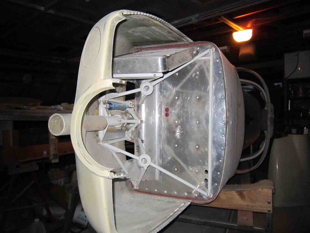
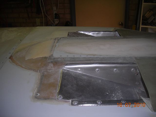
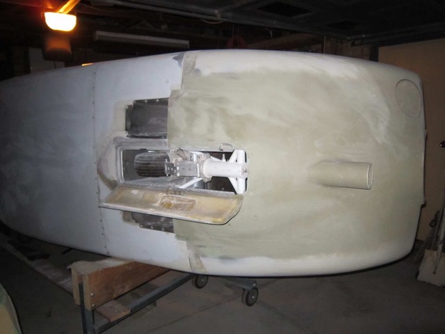
The cowl exits are ramps. When the front gear is down there is significantly more exit area. There is about 36in2 of exit area (Gear door closed). Inlet area is currently 17in2 (right cheek) feeding water exchanger and 7in2 (lower round intake) feeding oil cooler. 7in2 of Left cheek feeds air into the filter / throttle body, leaving about 10in2 of the left cheek blanked off at present.
The Prop is a second hand electric adjustable from New Zealand. They are no longer available. Its performance is unknown at this stage. The design was taken over by Phil at www.sprintaero.com .
Have you heard of anyone using electric fans for on the ground running?
Cheers Steve Izett
Steve, You could try using SCAT ducting to route any unused inlets over to the water to improve the volume of air. What do your cowl exits look like? In order to really know how everything is working you are going to have to fly. It will be difficult to do a full power takeoff and then go into high speed cruise and have the cooling work perfectly for both conditions unless you have cowl flaps or some manner of controlling the air. I currently accept 210-220 on takeoff in order to get 180-190 in cruise. That plane is going to be fast! It looks like 200K just sitting in the hangar! What prop is that? Bill
From: Rotary motors in aircraft [mailto:flyrotary@lancaironline.net]
Sent: Tuesday, November 15, 2016 3:13 AM
To: Rotary motors in aircraft
Subject: [FlyRotary] Re: Cooling Hi there Bill. The water exchanger is ~540 cubic inch in capacity and fed from the right cheek via a rotating trumpet shaped diffuser which in turn feeds a wedge. The oil exchanger is a turbo RX7 unit of 190 cubic inch capacity and fed via a trumpet/wedge diffuser fed from below the spinner.
I’ll send some pictures separately as they are together to large.
Steve,
Can you share any photos of your cooling install? Oil and water.
Bill
-----Original Message-----
From: Rotary motors in aircraft [mailto:flyrotary@lancaironline.net]
Sent: Monday, November 14, 2016 4:21 PM
To: Rotary motors in aircraft
Subject: [FlyRotary] Cooling
Hi guys.
The Glasair SIIRG is near completion and we are taxi testing.
The OAT is rising as we enter summer. Yesterday was 37C ~ 100F.
She can idle forever with water stabilising below 220F and oil below 180F if
the OAT is below 70F but not sure yet about the warmer days.
I'm wondering about 3 options and would value your experience and thoughts:
1. Route some more air from the left cheek into the water heat exchange
diffuser currently fed by the right cheek. I am currently only using 50% of
the left cheek (Blanked off). The other 50% of the left cheek feeds air to
the engine. The air is likely not to want to do the gymnastics required to
travel the path available.
2. Install another small core fed by the available left cheek air with water
from the heater outlet. This would make for easy plumping as far as the
water system. I'm not sure how much heat we could reject from that small
diameter heater outlet?
3. Install an electric fan on the main exchanger for extended on the ground
running. Main concern with fan is, what happens when cruising at up to
200Knots?
Appreciate you feedback
Steve Izett
Glasair SIIRG Genesis 4 port RD1C EC2
Perth Western Australia
--
Homepage: http://www.flyrotary.com/
Archive and UnSub:
http://mail.lancaironline.net:81/lists/flyrotary/List.html
--
Homepage: http://www.flyrotary.com/
Archive and UnSub: http://mail.lancaironline.net:81/lists/flyrotary/List.html
|