|
Tuning is a fascinating mixture of science, technology,
myth and aggravation - not necessary in that quantity order. RAM tuning
draws on the principals of Finite Amplitude Waves (FAW) and/or Holmsman
(harmonic) tuning.
While the Renesis can not benefit from the very robust
pulse generated by exhaust gases/pressure still remaining in the combustion
chamber when the intake opens (Dynamic Intake Effect), the same basic RAM
tuning principals are still there to be used.
For example when the intake opens - a refracted
(negative) pressure wave is generated which heads back up the intake tube.
Because it is a refracted wave it induces air molecules to move opposite of its
direction - in other words toward the intake where you want the air molecules to
flow. When this FAW hits a cross sectional area change (such as the intake
opening into a plenum or the atmosphere), two things occur.
1. An appreciable amount of the FAW pulse's energy
is reflected back down the intake
2. If the cross section is open and significantly
larger than the tube, the nature of the FAW pulse changes from a refracted wave
to a pressure wave, the pressure wave tends to induce air molecules to travel in
the direction the pulse is traveling - in this case back toward the intake
port. There depending on its arrival time relative to intake port action -
it may either help push more molecules into the combustion chamber or aid in
reducing reversion (reducing amount of charge the rising rotor pushes back out
the intake port on its upward compression stroke).
In the old 13B, Mazda's papers showed a 15% improvement in
power at 6000 rpm using this principal - in large part due to the contribution
of the very strong pulse caused by the overlap of the exhaust/intake cycle -
which with the side ports of the Renesis no longer exists (at least to the
degree it does in the older 13B). But the FAW principals and pulses still
exists in the Renesis intake.
Now if the length of the intake tube is the correct
length for the rpm sweet spot - these FAW pulses can increase your intake
volumetric efficiency even above 100% and in any case certainly
help.
This effect is generally only good for one rpm based on
the length of your runner - Mazda got two or more sweet spots by having some
valves that changed the effective length of the runners.
There are "only" three primary factors - the rate of
opening/closing of the intake port (combination of port shape and rpm), the
length of the runner and the speed of sound (which the FAW travels at).
One important thing - the FAW is a pulse of energy - it ripples along the air
molecules at the speed of sound, but do not confuse it with the actually
mass flow of the air (much lower in velocity and the two may be traveling in
opposite directions.). Also what helps you at one rpm may hurt your intake
at another rpm, so best to chose your desired operating sweet spot with some
thought.
I chose take off and climbout - others may choose top
speed. The rpm and therefore the tube lengths are unlikely to be the same
for both.
Example on the old 13B with a Racing Beat Street port the
intake started opening about 10 deg after TDC and was fully open by 32 deg after
TDC. The refracted pressure wave would be generated during that opening
phase and start back down the intake. If the rpm were around 7000 rpm and
you wanted the return pulse to arrive by the time the port had fully opened (32
Deg ATDC) then the pulse would have 32 - 10 = 22 deg of rotor rotation to get
generated, travel down to the plenum and get reflected back to the port just as
it became fully open. At 7000 rpm this would take a runner of approx
10.37" length. Lower rpm would take longer runners and higher rpm shorter
runners. Only an example using the older 13B - the Renesis would very
likey require different lengths depending on its side port opening/closing
profile.
In reality, the older 13B had the pressure wave travel
from the intake port of one rotor to the intake port of the second rotor rather
than having it be reflected by a plenum. This had some nice advantages
that the Mazda engineers took advantage of.
I do not have the Renesis port timing values to
apply, so this example would only apply to the old 13Bs. If the intake
opening profile is more radical (swifter) in opening in the Renesis than
the older 13B due to their side port location - then its possible the runner
lengths could be even less.
Anyone have the Renesis intake port timing
figures???
Ed
Sent: Friday, April 22, 2011 4:47 PM
Subject: [FlyRotary] Re: FW: [FlyRotary] Improved performance of my
new (2009) intake manifold
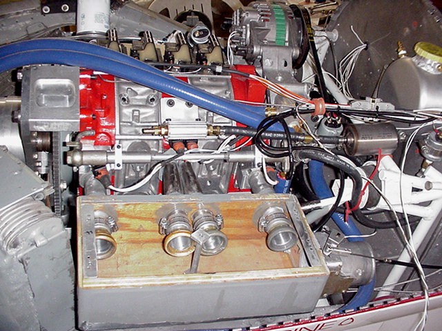
If Rhino is talking about the RV-4 ('RV Otter'), attached is a
shot shamelessly copied from Tracy's web site:
http://www.rotaryaviation.com/images/Renesis/Shoebox_1_08_08_2004.JPG
More
of Tracy's images here:
http://www.rotaryaviation.com/renesis_engine.htm
If
I've understood Tracy correctly, the tubes now extend almost to the other side
of the box, but the basic concept is 'dirt simple', with only tuning length an
issue. Since the Renesis can't really benefit from the massive exhaust
reverse-pulse into the intake that exists in the older 13B, this manifold
concept looks really attractive to me.
Charlie
On
4/22/2011 1:37 PM, H & J Johnson wrote:
Rhino are we talking the Rv8 intake or the Rv3?
Jarrett Johnson
www.innovention-tech.com
----- Original Message ----- From: Rino <lacombr@nbnet.nb.ca> Date:
Friday, April 22, 2011 11:29 am Subject: [FlyRotary] Re: FW:
[FlyRotary] Improved performance of my new (2009) intake manifold > If you
want simplicity and effectivity, look at Tracy's intake
> manifold.
> Rino Lacombe
>
>
> ----- Original Message
-----
> From: H & J Johnson
> To: Rotary motors
in aircraft
> Sent: Thursday, April 21, 2011 5:53 PM
> Subject: [FlyRotary] Re: FW: [FlyRotary] Improved performance
of
> my new (2009) intake manifold
>
>
>
Bill that is a pretty wild looking manifold! I can see that it
> was
intended to benifit from DIE? I've been leaning more towards a
> close
fitting 'over the top' manifold
>
> which would be usable
for either pusher or tractor installs,
> however it would be somewhat
simpler than the pictured unit. It
> would take alot of 'study' and
prep work to
>
> get a cast unit in that configuration.
More than likely it would
> need to be hand fab'd and welded [same as
what is pictured]. This
> is 'doable' but the added cost of getting
>
> all those parts together and into a working unit,
would push the
> cost up past the 'reasonable' level. At least as far
as i can tell
> from a your picture. Of course I could be seeing
>
> more complexity there than actually exists. However,
that being
> said I'm open to all options and suggestions on how it
could be
> made to work! :)
>
>
>
>
Best regards
>
> Jarrett Johnson
> www.innovention-tech.com
>
>
>
>
>
>
-------------------------------------------------------------------
>
-----------
>
>
> Jarrett,
>
>
>
> If you want to build an intake
manifold, I suggest you build one
> that works well like the one Dennis
came up with or if he has a
> better idea now, try it.
>
>
>
> See the attached msg.
>
>
>
> I believe that you would have to
build this for $500 or so to
> sell many and it would require at least
3 iterations, 13B,
> Renesis, and 20B. I assume all the early 13B
intakes are the same???
>
>
>
>
Bill B
>
>
>
>
>
-------------------------------------------------------------------
>
-----------
>
> From: Rotary motors in aircraft [flyrotary@lancaironline.net] On
> Behalf Of Dennis Havarlah
> Sent: Wednesday, November
10, 2010 3:27 PM
> To: Rotary motors in aircraft
>
Subject: [FlyRotary] Improved performance of my new (2009)
> intake
manifold
>
>
>
> As some of you
know I started flying my RV-7A with a cut - off
> Renesis intake
manifold. In 2009 I installed an new intake
> designed to route
pressure waves from the closing of rotor #1's
> intake into rotor #2
just before rotor #2's intake closed. After
> using the new
intake for over a year I am still very happy with
> it's performance.
>
>
>
> I gained about 15 mph
TAS at the same altitude and manifold pressure
>
> My
static engine rpm increased 300 to 350 rpm.
>
> My
takeoffs are faster and shorter with noticeable increase in
>
acceleration
> My climb rate increased
>
> My
oil and water cooling is more critical now because I make
> more HP.
>
>
>
> But - I must confess I
don't believe the manifold can be
> reproduced economically. It's
just too complicated.
>
> I also believe it should have
slightly shorter intake runners to
> increase the performance at higher
RPM. Decreasing the intake
> runner length probably would require
complete new geometry of the
> system.
>
>
> I have another concept for designing a Renesis intake that
using
> a reflected wave from Rotor #1 returning to Rotor #1
.
>
> I believe it would be much easier to
build and small enough to
> fit into the James rotorary cowl but
because my intake works well
> I am not moving ahead with completing
the design and building it.
>
>
>
> Dennis Haverlah
>
>
>
>
>
>
>
>
>
> -------------------------------------------------------------------
> -----------
>
>
> --
>
Homepage: http://www.flyrotary.com/
>
Archive and UnSub:
> http://mail.lancaironline.net:81/lists/flyrotary/List.html
>
>
>
-------------------------------------------------------------------
>
-----------
>
>
> --
> Homepage:
http://www.flyrotary.com/
>
Archive and UnSub:
> http://mail.lancaironline.net:81/lists/flyrotary/List.html
--

Homepage:  http://www.flyrotary.com/

Archive and UnSub:   http://mail.lancaironline.net:81/lists/flyrotary/List.html
|