|
Hi Bryan,
Here is a link to a web page which does a better
job of explaining the use of pulse tuning and I think addresses the problem
closer to what a PP intake might involve - using a plenum(s) rather than
attempting to interconnect the two intakes.
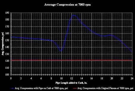
This page provides a graph which shows the dramatic
increase in compression pressure when you hit the sweet spot in Pulse
tuning
One thing to keep in mind is this analysis is
directed at at 4 stroke pistion engine and not the rotary - the principle
diffierence is the rotary engine provides twice the frequency of excitation at
the same rpm of the piston engine. This can be a factor in some of the
equations.
In any case, their experiment with pulse tuning
resulted in this conclusion -
From the results of the experiment, it was clear that the increase
in VE due to the pulse effect of the primary pipe is between 10% and 15% at 7000
RPM.
The Mazda DIE approach is a bit different in that
instead of an open (plenum) at the end of the tube and the need to wait the time
to have the pulse reflected back to the intake port, the rotary instead
has another intake port. This means that for the for the Mazda DIE effect
the tube can be 1/2 the length calculated for a port-to-plenum back-to-port
arrangement as you would have in a PP set up.
There are other factors that can shift the rpm
sweet spot that are tough to quantify without a computer program (they do exist
for around $600 the last time I checked) that can run on a PC.
Ed
Ed
----- Original Message -----
Sent: Monday, June 21, 2010 10:41
PM
Subject: [FlyRotary] Re: Pulse Tuning
[FlyRotary] Re: 13B rotary engines
Thanks
Ed,
Now that you mention
it, I recall seeing an engine with a very long intake at about a 45 degree
angle. I think it was only for a dyno run. Unusable for just about
any application due to its length.
I need to re-examine
that Renesis manifold.
Bryan
From:
Rotary motors in aircraft
[mailto:flyrotary@lancaironline.net] On
Behalf Of Ed Anderson
Sent: Monday, June 21, 2010 10:03
PM
To: Rotary motors in aircraft
Subject: [FlyRotary] Pulse Tuning
[FlyRotary] Re: 13B rotary engines
BW, as best I recall (don't have a
Renesis) that small chamber is simply a "transfer chamber" to get the pulse
from one intake tube to another.
The DIE effect that Tracy mentions relies on
a type of pulse called a "Finite Amplitude Wave (FAW)" - this wave behaves
different from traditional sound waves and makes a 125 db sound wave seem lik
a very tiny soundin comparison. These wave shatter metal not to mention
ear drums.
There are several "tuning"
techniques which attempt to make use of these Finite Amplitude waves in
induction systems. Mazda has been one of the most successful attempts in
part due to its unique construction (no valves) and the rapid generation of
these waves in the intake. In the older 13B anytime the intake port
opened, the still present exhaust gases would burst forth and produce a shock
wave ( FAW pulse). If the intakes were tied together and of the
proper length - at a specific rpm the pulse generated by the opening of the
intake of one rotor would travel through the intake to the intake of the 2nd
rotor. It was designed to arrive just as the intake port was
closing.
When an engine (piston or rotary)
starts its compression stroke, the intake remains open for a period - during
this period the compressiing piston/rotor pushes out some of the mixture its
already "sucked" into the chamber. Typically the value for this mixture
pushed out during this "Reversion of flow" amounts to around 15% of the amount
already "sucked" in.
So if the FAW Pulse arrives at the
right time most of its dynamic energy is converted from kinetic energy to a
localized increase in pressure right beside the closing intake port. If
all goes well it prevents most of this reversion. In fact, Mazda found a
15% increase in HP at 6000 rpm using this
knowledge.
However, it is generally only
significant for one rpm - or if you do like Mazda and have a valve to change
the length of the intake for this pulse, you may get two sweet spots at a
lower and a higher rpm.
Since PP are not interconnected
the approach Mazda used on the N/A 13B side ports won't work as
is.
However, due to the properties of
the FAW pulse when it encounters a change in cross sectional area, the pulse
tuning technique could theoretically be used on a PP. Since you want a
increase in pressure as the port closes, and since the FAW pulse will reflect
from an opening into the atmosphere (Plenumn box also) - if you made your PP
tube a specific length then at some rpm (which can be calculated) the pulse
will bounce back from the plenumn and reach the intake port at exactly the
correct time.
That said when one makes the
calculations (as best I recall from a few years ago - so don't hold me to
exact figures), you would find that say for the peak to occur at 6000 rpm -
your PP tube would need to be around 48" long. High target rpm would
result in smaller lengths required.
Then again, that length (whatever
it is) is only good at one RPM to get the
effect.
In my case, I spent 3 months just
doing the analysis to derive the equations for the old 13B. Since my
primary objective was power on take off - (I really don't care about top speed
as I don't fly there - too expensive {:>)), I did not mind the restriction
to one rpm.
So my DIE intake is tuned to give
maximum power at around 6000 rpm (My static for take off swinging a 74x88
prop). I may get up to 6200 rpm static on a colder day as the sweet spot
is a function of the speed of sound (among other things) which changes
with OAT temperture.
In my opinion (and that is all it
is), if I were going PP, I would probably not spend much time considering DIE
(or Dynamic Chamber -- which is not quite what most people think it
is).
----- Original Message -----
Sent: Monday,
June 21, 2010 8:38 PM
Subject:
[FlyRotary] Re: 13B rotary engines
Thanks Tracy,
I didnt realize
the plenum would have that effect.
The stock Renesis
seems to have a chamber prior to the valves that create the DIE, but I guess
it is too small to be called a plenum chamber.
BW
From:
Rotary motors in aircraft
[mailto:flyrotary@lancaironline.net] On
Behalf Of Tracy Crook
Sent: Monday, June 21, 2010 8:12
PM
To: Rotary motors in aircraft
Subject: [FlyRotary] Re: 13B rotary
engines
I
hate to ask, but what about the Dynamic Intake effect in the PP with a
traditional log-type manifold?
If you
think about the meaning and function of the Dynamic effect, you will see
that it is mutually exclusive with the traditional log-type
manifold. the 'log' is a plenum chamber which inherently damps
out the dynamic waves and reflections in a DIE intake system.
The
timing, length, etc would be different than for the sideport DIE setup that
Ed Anderson did so much work on. I won't even pretend to have any idea
what the proper parameters are for a PP DIE setup.
Tracy
On Mon, Jun 21, 2010 at 7:44 PM, Bryan Winberry
<bryanwinberry@bellsouth.net>
wrote:
Yeah,
I just saw those MP
taps for the oil injection on another site. Im no expert, but that
seems like an odd place to gather MP data.
I only asked about
the slide throttle, I certainly had not decided that it was the
answer.
Sounds like you
recommend the traditional TB manifold runners setup for the PP as
well.
I hate to ask, but
what about the Dynamic Intake effect in the PP with a traditional log-type
manifold?
Bryan
From:
Rotary motors in aircraft
[mailto:flyrotary@lancaironline.net] On Behalf Of Tracy Crook
Sent: Monday, June 21, 2010 7:29
PM
To: Rotary
motors in aircraft
Subject: [FlyRotary] Re: 13B rotary
engines
I have purchased
the EC-3. Will this make any difference in the difficulty of
tuning? Is it a good choice for a PP
setup?
Id imagine I
should aim for around 7500 rpm for a
RD-1C.
Bryan,
Mark (the Mustang II w/ pp 13B) used an EC2 on his engine and eventually got
it running pretty well but it was a MAJOR pain getting it to work with that
slide throttle since getting manifold pressure was hard to do since there IS
NO MANIFOLD when using that slide right at the port. No one seems to
consider these 'details' when planning their installation. I'm of the
same opinion as Bill on the slide throttle- Why the hell do it?
Mark eventually got a usable MP signal by taping into the oil injection
ports in the rotor housing but that's not ideal.
BTW, several
people referd to Mark's PP 13B as a Renesis PP but I thought it was a 2nd
gen 13B. I could be wrong. Pity that the airplane was lost in
that ground accident, I had not heard about that.
Tracy
On Mon, Jun 21, 2010 at 7:13 PM, <wrjjrs@aol.com>
wrote:
The importance of
any system that you use will be, DO YOU UNDERSTAND IT? Have you ever
tuned an engine using a carb, or FI yourself? Tracy's system seems
like a good one for the price. I have not used Tracy's EMS but it has
been effective for the guys that keep at it. A good fuel flow and mixture
meter are top tools for determining where you are. I believe those are built
into the EC-3. Remember, while it won't be changing while you run the
engine, the intake and exhaust are just as "active" parts as ignition and
injection. My advise would be to be sure that you triple check all your
wiring before you install it. Too many of the guys have run into problems in
their wiring. Be sure you are dealing with a genuine tuning problem and you
will be miles ahead.
I have purchased
the EC-3. Will this make any difference in the difficulty of
tuning? Is it a good choice for a PP
setup?
Id imagine I
should aim for around 7500 rpm for a
RD-1C.
-----Original
Message-----
From: Bryan Winberry <bryanwinberry@bellsouth.net>
To: Rotary motors in aircraft <flyrotary@lancaironline.net>
Sent: Mon, Jun 21, 2010
3:50 pm
Subject: [FlyRotary] Re: 13B rotary
engines
I have purchased
the EC-3. Will this make any difference in the difficulty of
tuning? Is it a good choice for a PP
setup?
Id imagine I
should aim for around 7500 rpm for a
RD-1C.
As a reference the
original Powersport 13B P-port is rated at 210 HP normally aspirated. The
fuel flows are very similar to any other engine producing that level of
power. Steve tells me that they were seeing FF very comparable to an angle
valve IO-360 producing identical power. This engine was dynoed with
butterfly valves in the housing. These p-ports were 1-5/8' diameter
optimized for 6000 RPM. The engine would rev higher but you were already at
peak power anyway. Larger ports will make more power at higher RPM. Tuning
will become more critical with the larger ports. A personal anecdote
here. I built a high reving motorcycle engine in 1978 with all the "best"
parts at the time. The engine was unreal at high revs, but if you
transitioned to anything below 4000 RPM by shutting the throttle off and
quickly opening it again the engine would "catch" or hit an RPM
plateau and would rev no higher. In fact the engine would die if not
returned to idle! This horrible malfunction was TUNED OUT later, and the
solution was surprisingly simple, however difficult to find. The key
here is that many people underestimate the job of installing and tuning
p-ports. There are two aspects, first the initial install being sure there
are no leaks . Then second, and most overlooked is that the system must
tolerate the heat cycles of a high power engine without DEVELOPING NEW LEAKS
for a long time. Powersport used an insert with o-rings sealing the port.
O-rings or other elastomers work much better than epoxy on long-term sealing
because there are different expansion rates between the port and the epoxy.
On a car you can usually get away with epoxy for a while. An aircraft
is a different animal. The aircraft engine needs to tolerate 80-100%
power for long periods and then long cold-soaks on the ground. The
rotary is mechanically tough enough but you need to design your subsystems
like a race car that will see a 500 mile long straight-away! When
Paul Lamar ran one of the newsletter guys P-port Renesis at MazdaTrix, They
got great numbers, but only after changing to an intake that MazdaTrix had
spent lots of time tuning. P-ports will run great, and even idle well if not
too oversized, but don't expect the tuning to be real easy. Remember you are
designing a new intake, exhaust, and the equivilent of a new cam timing all
at once. The rotary is very much like a two-cycle in that respect. The
results can be very worth while if you understand the difficulty
involved.
Not all P-ports
are equal.
Talk to Bill
Jepson ( on here) about availability of new
P-ports.
All this talk of
additional power coupled with an easier intake design has me thinking I
should probably go this direction with my Renesis. Its still on the
stand after rebuild.
I havent
constructed the manifold yet
anyway.
I assume fuel
flow will be higher than normal?
Is slide throttle
best option?
Need to search
archives I guess.
From:
Rotary motors in aircraft [mailto:flyrotary@lancaironline.net] On Behalf Of Lynn Hanover
Sent: Monday, June 21, 2010 12:15
PM
To: Rotary motors in aircraft
Subject: [FlyRotary] Re: 13B rotary
engines
In a message dated 6/21/2010
11:03:01 A.M. Eastern Standard Time, rv-4mike@cox.net
writes:
Thanks for
the feedback Lynn. Unusual to see a "poor port
design" actually aid
performance.
It is not obvious until you start
graphing the open and close events, but the side port which uses the side
of the rotor as a shutter to open and close the port, offers Mazda great
latitude in port timing. In the periphery ported engine (both ports)
it is impossible to arrive at zero overlap, and have an engine that will
produce any power at all. The apex seal does not close off either port at
all, it just valves gasses in one direction or another.
In addition, the overlap of the
periphery ported engine is far more effective flow wise than overlap in
the side ported engine. One apex seal is above the intake port when the
opposing apex seal is below the exhaust port. Flow between the two is
unobstructed.
So, at low RPM you get fresh mixture
leaving through the exhaust port, and combinations of burned and unburned
fuel and exhaust gasses flowing partway back into the intake
runners.
This reduces the low RPM output to
the point that the engine seems quit docile, and is easy to drive around
in the car, slowly, or possibly taxi in an aircraft. This would make
off idle tuning data useless as there will be fuel burning right on top of
the EGT probes, and unburned fuel reaching the F/A sensor.
The engine will act along the
lines of a piston engine with a long duration cam. When the engine reaches
its happy RPM where all of the mixture is burning inside the engine, it
will step up on the "CAM" and you will
see what a good idea this was. Use slow throttle inputs until you find the
"WOW" RPM, and be ready with all available rudder.
When we first ran a factory
periphery port engine, we found that there were places on the track that
would not allow full throttle. This with 11" wide slicks. Thank Heaven for
rev limiters. The driver reported the rear end getting real loose cresting
hills and bumps.
7000comp_graphsmall.jpg
|