|
Here´s what I did:
I bought a couple of expensive 90 deg. static port
inserts and ground them down, so they were actually just a 90 deg. metal
channel, ending in a hose fitting. I could have saved a lot of time and $ if I
had just bought two AN842 elbows, but I was not that clever back
then.
Here you see the positions marked on the inside of
the fuselage. I removed the core material around the positions and, probably,
covered with 2 BID.
Then I drilled a 1 mm. or so hole, inserted a loose
oiled drill bit from the outside, hung the ground down static port (AN842
elbow) on the drill bit, secured it with a dab of instant glue and
finally
locked it in place with flox and, maybe, one BID,
leaving the hose fitting free, of course.
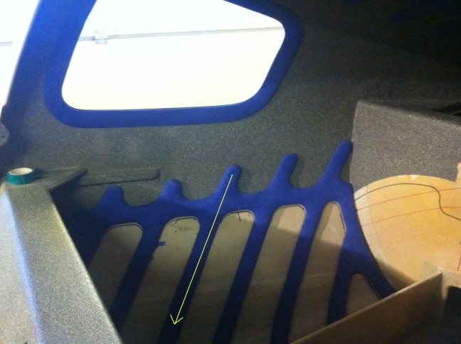
I had carefully planned my fish bone interior to
match the static ports, so that they, and the static line, would be covered by
one of the "bones".
The matrix for the "bones" is fabricated on the
fuselage and is made of 2 or 3 BID on release tape. The "bone" that houses the
static line is covered with 1/4"
white foam on the front, nicely rounded and covered
with 1 BID. The rest of the "bones" are covered with 1/4" soft foam padding and
everything is wrapped in
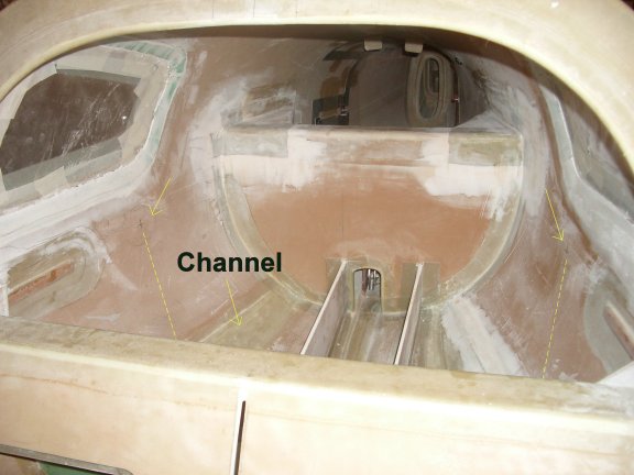
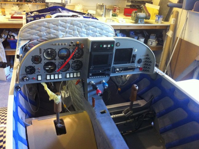
blue alcantara. I then carved a channel for the
static line from the backside. The static line runs down into the cable channel
below (see first photo), that consists of
the coreless area with a 2 BID cover over
it.
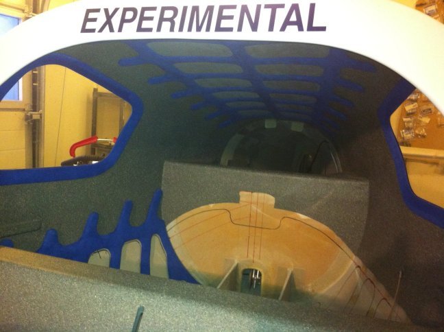
This is what it looks like when finished. First a
layer of 1/4" soft foam is glued to the fuselage. Grey alcantara glued on top of
that.
Channels carefully cut where the blue matrix is to
be fixed to the fuselage. Velcro part 1, maybe 5/8" strips, glued to fuselage in
those channels,
velcro part 2 glued to blue matrix.
Same procedure for the headliner. You can see the
static line on the LH fuselage side (RH side of the photo if viewed from
Australia).
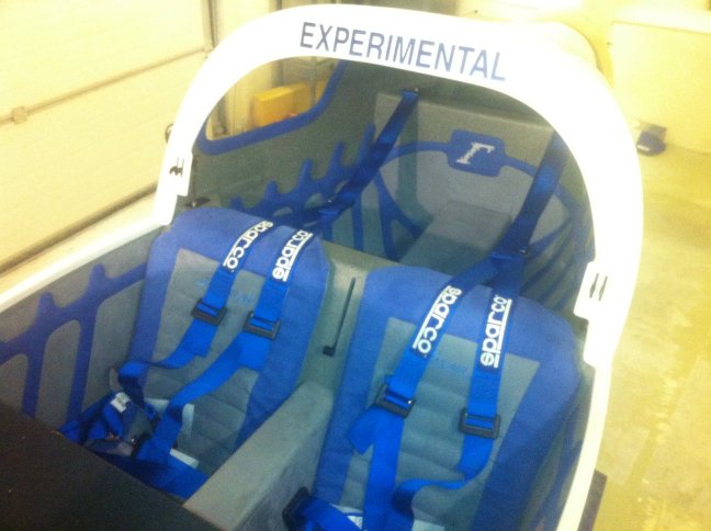
I did the side panels for the seating area slightly
different, mainly because of the rudder cables and stub wing
opening.
I first fabricated a flat 2 BID panel on the table.
I then cut it to shape and double curved it, which was a bit of a pain. I had to
make several cuts
from the outside towards the middle of the panel,
fix it to the fuselage with hot glue and cover the cuts with 2 bid, in order
to produce a shape that
fit the fuselage nicely. I then covered the panels
with soft foam and grey alcantara and then velcro-installed the blue "bone"
matrix, that I had pre-made directly on the panels.
This way I have two loose panels (yes, installed
with velcro) that also close the stub wing opening.
The foot wells and nose gear well are just covered
with some helicopter padding that is cut to shape and folded over and sewn at
the edges.
IMPORTANT:
"Bone" matrixes and window frames must be
fabricated on release tape in the exact spot they will be installed!!! It
is NOT possible to just make
a flat piece of 2 BID, cut it to shape and install
it with velcro. All surfaces are double curved.
All in all, I think it is a nice result. It is
rather time consuming, though, but it is good fun, lightweight and inexpensive.
No sewing required, this is a job you can do, and do nicely,
without involving professionals.
Regards
Tim Jorgensen
Denmark
360MKIIOBFB / 100%, waiting another week or so for
the flight permit.
1.jpg
2.jpg
3.jpg
4.jpg
5.jpg
|