|
|
Preamble:
All aircraft , turbine and
reciprocating, should pass a fuel supply
flow test prior to first flight. A pump and regulating valve should be
configured to draw fuel from the airframe at the maximum anticipated
rate until the airframe fuel is exhausted. The aircraft deck angle
should be the same as the deck angle experienced during a go around.
You should test for the condition that would arise at the end of a
flight where you are on your third approach at the alternate airport
with critical fuel and you are forced to go around. Full power, high
deck angle, low tanks is not the time to find out you have 5 gallons
less usable than you thought.
What follows is a discussion of the existing L-IVPT fuel system (w/
belly tank)
and how it can be configured to reduce the opportunity for pilot /
operator error.
DANGER: This is a long post on an obscure topic of interest to a
limited few. Reading on may cause drooling, incontinence or even death.
If death persists for more than four hours, call your physician.
Given that flames and Jet-A are only good in confined amounts, I want
to start by saying that the factory fuel system has demonstrated that
it is safe. It can be operated in all flight configurations and
performs as required. Certain aspects of the fuel system require the
operator or pilot to follow certain procedures in order to achieve the
desired level of operational performance. For example, a system with a
left –right selector requires that the pilot select the correct tank at
appropriate intervals in order to use all the available fuel. If the
pilot fails to select the correct tank an unsafe situation may result
that is not due to the intrinsic safety of the fuel system.
As a staunch believer in the fallibility of humans it is my policy to
minimize the opportunity for human and mechanical failures in systems
design. It is my opinion that the current L-IVPT fuel system
can be
improved to reduce the opportunity for operator error and mechanical
failure.
The current system treats the belly tank as a bulge in the fuel line
between the wing fuel selector and engine. Think of it as a very short
and very fat piece of fuel line. Because of its volume, air or vapor
can accumulate. This gas is dealt with by an electrically operated
normally open solenoid in the vent line. The solenoid is connected to
the master switch and is therefore closed in flight and open on the
ground. This is all very reasonable in concept.
This system can suffer several problems as a result of operator error
or mechanical failure. The solenoid valve can fail to reach the desired
state by a mechanical jam due to contamination, an electrical fault,
and failure to turn off the battery master during fueling, or, in cases
where a switch is added to the solenoid circuit, failure to have the
switch in the correct position. Solenoid failures can result in either
gas being retained in the belly tank or fuel being discharged
overboard. Trapped gas on the ground expands to a larger volume during
climb (remember that unfortunate burrito incident), possibly starving
the engine by preventing wing to belly fuel flow.
There are two other significant failure scenarios that may result from
operator error. Depending on belly tank volume and line configuration,
an empty belly tank may take as much as 50 minutes to fill (reported by
Lancair). Turning on the master before all trapped gas has vented (and
the belly is full) will shut the vent, trapping and vapors and reducing
the usable fuel volume. The other failure may result from the pilot
setting the fuel selector to the “OFF” position during flight. Now fuel
is being evacuated from the belly with no air being introduced to
replace it. Remember in science class where you put a little water in a
gallon can, heated it to the boiling point and then sealed it, removed
the heat source and watched the atmospheric pressure crush the can as
the vapor condensed? Now imagine that happening to the belly tank.
Another failure (not operator induced) could be an air leak from the
pressurized cabin into the belly tank, again displacing fuel with air.
Flight testing has also shown that in the factory configuration, fuel
will not flow from the wing to
the belly tank with sufficient rate due to static head pressure
alone. Supplemental differential pressure from the engine fuel pump
(suction) or the wing tip NACA scoop vents is required. It should be
noted that at
200KIAS the pressure recovery of the NACA scoops is on the order of
>0.7 PSI (>15” head pressure) estimated. At 90 KIAS this pressure
drops by
80%. It is this NACA recovery pressure that mandates the solenoid valve
in the belly tank vent line. Without it the pressure would force fuel
out the vent line during cruise flight or decent.
An improved system would have the following features:
The gravity only filling rate of the belly tank should exceed the
maximum engine demand rate with chilled (-40) fuel (see my posting on
fuel viscosity and temperature). A reasonable minimum flow rate may be in the 1
GPM range (60GPH) combined from both wings.
The belly vent should be able to allow gas to flow bi-directionally
with minimal pressure drop while preventing fuel from venting overboard.
Pilot interaction should be limited to selecting Left or Right wings. A
Both selection should ONLY be available if it can be demonstrated that
all available fuel can be used in all flight configurations when Both
is selected. Byzantine fuel systems with multiple valves and
configurations should be avoided.
The belly tank should have a level indicator. At a minimum this would
be a warning light at the ~80% level, indicating the presence of air in
the belly tank. A second known volume warning would be better and an
actual capacity gauge would be best.
In practice it would be best to bifurcate the belly tank with a fore to
aft vertical septum at the centerline. Large diameter lines (>5/8”)
would connect the wing root to the belly tank. Belly tank vent lines
would be routed with a positive grade from the belly tank to the top of
the wing root bay. A pickup at the belly low point (with slosh doors)
would feed a selector valve. In this configuration the belly tank(s)
become extensions of the wing tanks and can be considered just another
bay.
In reality there are several aircraft where changing the fuel
configuration would be impractical. So, the question becomes “Is there
a better configuration available without opening the belly tank or the
wings?” The answer is yes if the gravity drain rate and vent
requirements can be met.
The gravity flow rate (0.5 -1 GPM per wing) must be achieved without
allowing cross wing transfer of fuel during uncoordinated flight or
parking on a lateral slope. This can be achieved using high flow
coaxial low pressure check valves (think flap valve in a housing).
Configured properly with sufficient flow at low enough pressures and
low temperatures it may be possible to eliminate the selector valve
entirely and replace it with a simple On-Off valve feeding the engine.
Alternately the check valves could be replaced with On-Off valves or
coaxial solenoids but this introduces more opportunity for human error.
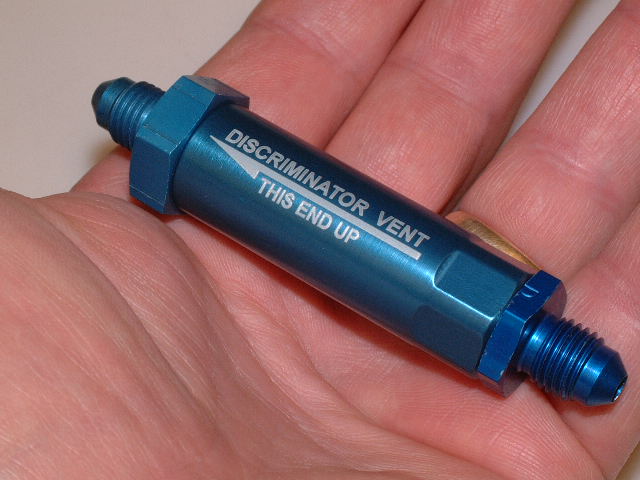
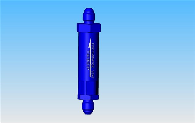
This brings us to the vent valve. This valve should allow gas to flow
bi-directionally with minimal pressure drop while preventing fuel from
venting overboard. I remembered a valve installed in the fuel vent
lines of race cars. It is called a discriminator valve and it uses a
ball that floats in the fuel which seats when it reaches the top of the
valve assembly. Air is free to pass but fuel floats the ball up and
closes the outlet.
During a recent visit to Lancair I mentioned this idea to Ross. Cleaver
guy he is he had already come up with the same idea and produced a
prototype valve using a thin walled hollow aluminum sphere. Using the
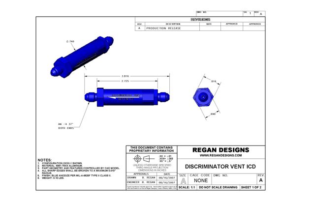
Ross sphere idea, I designed a check valve with a PTFE (Teflon) seat,
improved gas porting in a small package that uses
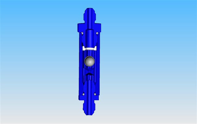
standard AN fittings. The attached pictures show the design. I built a
couple of prototypes to test to confirm performance. The axial passages
allow air to flow around the ball without lifting it off of its stop.
Air can flow through the valve at a rate of about 5 GPM without lifting
to ball onto the seat and closing the vent. A small coaxial hole
prevents the ball from hydraulically locking onto its lower stop.
Testing shows that the Discriminator Valve works as desired, closing at
the presence of fuel. A small (<3cc) amount of fuel may get past the
ball if the fuel has a lot of velocity when it reaches the valve or if
foaming has reduced the fuel density. I also tested with the valve
inverted to confirm that even a low flow rate would push the ball down
onto the seat. This is important if the aircraft comes to rest upside
down.
The Discriminator Vent would be mounted high on the firewall with its
discharge connected to a tube that would then discharge onto the
windscreen on the passenger side. This would alert the pilot if the
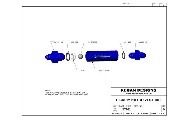
vent failed and fuel was venting overboard. The bottom fitting on the
vent can be replaced with a T fitting and nut to accommodate the two
belly tank vents. At least one of the lines must be routed entirely
below the height of the vent to prevent a fuel lock.
This vent will NOT work in systems where the gravity drain rate is less
than the engine consumption rate. In this case the engine can drain the
belly tank and suck air via the vent. See the preamble regarding the
need for qualification flow testing.
I have forwarded one of the prototypes, CAD models and drawings to Tim
at Lancair for his evaluation. If they agree that the design has merit
they will likely manufacture and supply the valve at a reasonable
price. The design is free to Lancair. I am doing this pro bono because
it takes me 2 days to analyze data and prepare an
accident investigation report for the NTSB. A task I do free of charge
and dislike immensely. It took me about 2 days to design, fabricate and
test this design so if it prevents one operator induced accident then
it is a break even deal for me. There is also that little thing about
not
notching another wreck.
Fly safe(r).
Regards
Brent Regan
Discriminator Prototype.JPG
discriminator section.jpg
discriminator vent icd s1.jpg
discriminator vent icd s2.jpg
discriminator.jpg
|
|