|
|
Some historical docs about the P51 say that one reason for placing the diffuser inlet aft under the wing (instead of near the prop) is to minimize pressure pulses from the prop. Each pulse from a blade causes in increase of pressure, but it also slightly compresses the air in the duct, which then expands (back out) between pulses, which interferes with flow, both from the next pulse and from regular flow. On the other hand, LoPresti (with his 'Holy Cowl') tried to take advantage of the pulses for *induction*. Remember, induction is different in that there are huge pressure/flow changes because of intake valving (whether there are actual valves in there or not :-) ). He claimed to position the blade/duct relationship so that pulses arrived at the valve coinciding with valve opening.
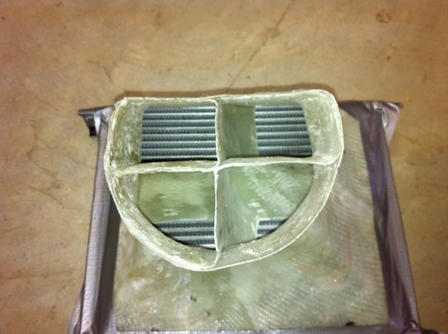
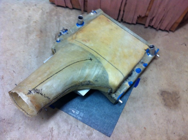
Warning: My fiberglass work is...ugly.   Pics of my turning vanes (hopefully) attached. Note that these diffusers have *not* flown. My testing was similar to Bobby's, with a leaf blower to feed the diffuser, but no pressure measurements in the diffuser. I used the 'traditional' method of a thread on a stick, moved around the exit side of the heat exchanger core, to determine whether I had fairly consistent flow across the entire core. I've got a video of the test, but it'll be too big to post here. I'll try to find a link to a cloud-based source if you want to see it. The rad turning van is an aluminum blade which follows the black marker line drawn on the outside of the diffuser. I had zero flow in the forward bottom 1/4 of the core before adding the vane (as expected) before adding the vane, and fairly even flow across the core after adding the vane. As previously discussed, a 'wedge' diffuser requires an extreme pinch in the wedge at the aft end, to keep flow working in the forward 2/3 of the core. If you've read the K&W chapter on cooling and seen their drawing of a wedge diffuser, it shows the opposite of my (and Tracy's) experience in required shape at the aft end of the wedge. I don't have an explanation for the difference, but I know that the K&W wedge shape doesn't work with a thin wedge.
The oil cooler diffuser is *very* short (~8") and very asymmetrical (cowl packaging restrictions). I never bothered to check without the vanes because the duct is so short and the turns so extreme I knew it would never work without vanes. Again, never flown, so I have no idea on total efficiency, but I do know that the core is getting even flow across its entire face.
Hope that helps,
Charlie
Matt,
“Bobby, how did you measure the good airflow? Magnetometers?” I used a large leaf blower pointed into a 4’ section of 6” tubing connected to the diffuser inlet. I then used an anemometer to measure exit air speeds in a grid pattern of
the core.
“Won't your ground cooling be harder with a belly mount, the further away from the prop ?” I believe prop blast / airspeed improves away from the prop root. At the bottom of my cowling I measured airspeed in the low 22-24 mph range at
low idle. No other supporting data. A large straight exit should improve ground cooling. The inlet duct placement on Russell Sherwood’s plane is reported to have excellent ground cooling with the larger inlet. I believe my inlet duct would be closer to where
Ross placed his.
My 48# MT (76”) electric prop is for sale if you need a nose anchor. I’ve come to the conclusion I can’t use it for the S21.
Bobby
From: Rotary motors in aircraft [mailto:flyrotary@lancaironline.net]
Sent: Thursday, January 28, 2021 8:11 PM
To: Rotary motors in aircraft
Subject: [FlyRotary] Re: Ross Farnham - Cooling video
This summer I will design a wireless circuit board that can do 6 temperature probes and 6 pressure ports running off batteries that will send data to cell phone/laptop for capturing. Give us real data to test
out different diffuser designs.
Charlie, any pictures of your turning vanes? I did a trumpet to wedge diffuser and I don't (only guessing here) think the wedge shapes work as well as they do. Will add some turning vanes to shoot more air into the front of the rads. You are right that I am
tail heavy and probably can't do a belly mount :( So the best bet is to get a thicker smaller rad.
Le Roux, I have talked with Alex a bunch over exit louvers on the side. We are hoping to tune the exhaust dumping better to help pull air out of the bottom of the cowl. I don't see too many exit louvers though on planes. Any reason for
it?
Bobby, how did you measure the good airflow? Magnetometers? Won't your ground cooling be harder with a belly mount, the further away from the prop ?
Bruce, how far along are you? The tango might be tail heavy like mine, have you done a W&B yet? I am skeptical on P-port = 250hp, very skepataple. I am 10kts slower than a standard lycoming engine in the tango 2, even being p-ported.
I have decided to use a belly mount radiator on my tango 2. Have been dithering around for ages without making a decision - Ross's excellent articles have convinced me
to go with this setup.
I have decided on 20” x 7” x either 68 mm 0r 81 mm The 68 mm (2 3/4” will give approximately 385 cubic” the 81 mm approx 455 cubic “ which is around Neil’s recommendation.
I have a P Lamar designed radiator which he was confident would cool up to 250 hp (two 1/2 “ wide cores adding up to 330 cubic “ so hopefully the thinner 68mm core should be okay given the lower drag and straight through flow characteristics I am looking
at around 63 “ length for the pod to improve flow characteristics - All constructive input welcome I am not sure about the best external shape! a very rough sketch is attached
On 28 January 2021 at 12:07:13, Matt Boiteau
mattboiteau@gmail.com (flyrotary@lancaironline.net) wrote:
Ross does the SDS EFI system and did 2 videos on cooling his Subaru engine.
https://www.youtube.com/watch?v=GGXXEgqhmmc&ab_channel=rv6ejguy
It seems him and Tracy agree that we need a thicker core, then the 1" Paul L kept on suggesting. My coolant rad is almost as wide as the plane with the 1" truck core.
I'm definitely not happy with my cooling setup, but needed to get moving and finish the plane. Can sit around all day talking about it, or start with something and get better in time. I'm done the flyoff hours in FL and hoping to bring the plane back to Canada
in the spring where I can tinker with it then. 3D draw things out and get suggestions from people then.
What do you guys think of a belly mount coolant rad? How would we plum the exhaust out of the way? Keep oil coolant in the cowl? Or Below the engine?
--
Homepage:
http://www.flyrotary.com/
Archive and UnSub: http://mail.lancaironline.net:81/lists/flyrotary/List.html
Disclaimer The information contained in this communication from the sender is confidential. It is intended solely for use by the recipient and others authorized to receive it. If you are not the recipient, you are hereby notified that any disclosure, copying, distribution or taking action in relation of the contents of this information is strictly prohibited and may be unlawful.
This email has been scanned for viruses and malware, and may have been automatically archived by Mimecast Ltd, an innovator in Software as a Service (SaaS) for business. Providing a safer and more useful place for your human generated data. Specializing in; Security, archiving and compliance. To find out more Click Here.
.JPG.jpg)
oil cooler vanes (Small).JPG
.JPG.jpg)
rad duct (Small).JPG
|
|