In my program, on startup you have the following entries:
Lower Left Corner
Left side of a given dimension
Right side of a given dimension
Length (as indicated on the source graphic)
The last three entries create a scale (pixel to inch).
From there it’s just a matter of selecting the tool (Line,
Polyline, Rectangle, Arc, Circle, Spline) and then click on the trace points.
The results can be saved to a script file or to your clipboard.
With this information I can place my engine proportionally in my
CAD drawing along with my scoop and make any adjustments prior to cutting any
material.
It also has the ability to zoom in and out.
I have a couple of quirks to resolve prior to release. I run
into problems when I select a tool but do not add any entries for it. The CAD
software complains.
T Mann
From: Rotary motors in
aircraft [mailto:flyrotary@lancaironline.net] On Behalf Of George
Lendich
Sent: Friday, February 05, 2010 3:21 PM
To: Rotary motors in aircraft
Subject: [FlyRotary] Re: Tiff to CAD Software
Impressive
- how do you check for dimensional accuracy and can it be reproduced in 3D, I'm
guessing it can.
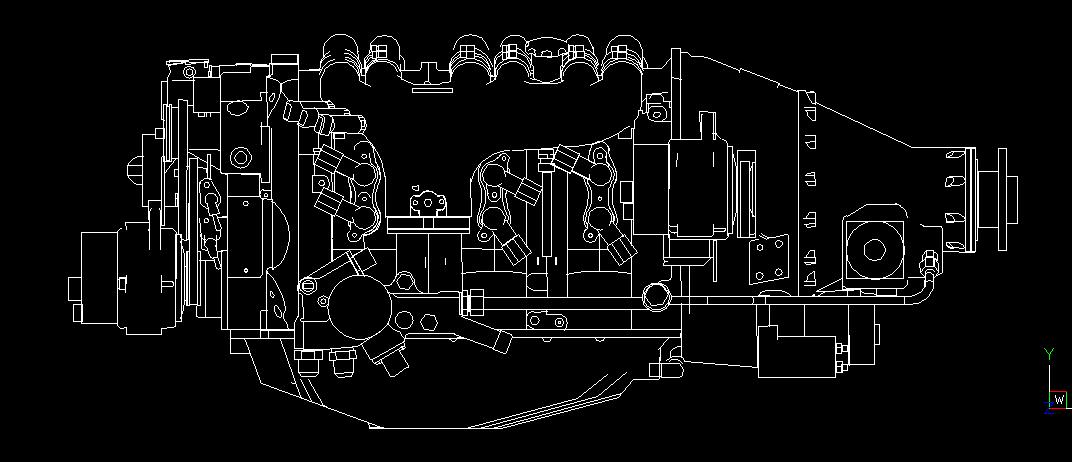
Just an Update on my Image-to-C AD project.
I used the Mistral G300 as a test image.
I generated the scripts from that and ran them in SolidWorks.
Here’s the result.
