|
|
|
Uh, a properly wired Oildyne pump has an internal thermal
breaker. I worry much more about shorting lines carrying
potentially high amperage current. If pump power were applied too
long (more than 10 seconds, yellow transit light on, either up or down
selected), I could always pull the breaker on my center console, just below my
throttle wrist. I never liked the other bad direction from Lancair -
mounting the pump breaker on the baggage bulkhead (remember John Denver).
The instructions had it mounted there because it was a short run from
the battery and master relay that was to be mounted back there
also. For me, it was natural to put the breaker on the center console
since my battery and master relay is mounted behind the co-pilot seat, a
mere 12 inches away.
Grayhawk
In a message dated 5/28/2009 7:44:22 P.M. Central Daylight Time,
snopercod@citcom.net writes:
Reply to
Dan Schaefer:
No flames from me. Everything you said was correct, but I
would like to
elaborate on a couple of your points.
In your home,
the function of a circuit breaker is *only* to protect the
wiring, as you
wrote. Your typical 20A circuit breaker will not protect
your garbage
disposal from burning up if something gets jammed in there,
for example.
That's why they have their own thermal circuit breakers
(that little red
button down there). In an industrial setting,
thermal-magnetic circuit
breakers are used to protect large motors, and
the 'heaters' are sized to
protect the motor in case of a locked rotor.
It's my belief that the
circuit breaker (or fuse) feeding the hydraulic
pump in the Lancair should
be sized to protect the pump from burning up,
in addition to protecting
the wiring, I believe that it *is* possible.
I have the specifications
right here for the Oildyne (now Parker) Model
108AA19-AL-3VT as used in my
Lancair 235. Unfortunately, it doesn't list
the locked-rotor current for
the series-wound 12V DC motor. The chart in
there says that the motor
draws ~15 Amps at low pressure, and about 40
Amps at 1500 PSI. It's my
vague recollection that the locked-rotor
current for this motor is a
little over 70 Amps, but I can't remember
where I came up with that. So
just now, I did the best I could to
measure it by replacing the 40A
Maxi-Fuse that I use to protect the
pump/wiring with 12" of 18AWG stranded
wire as a 'shunt'. From wire
tables, the resistance of that piece of wire
should be between .0055 and
.0065 ohms, but I have no way to measure it.
Using my Fluke 87-V, the
'peak inrush' (250 uS) across the 'shunt' was
0.90V, the 100ms peak was
0.50V, and the voltage while the gear was coming
up was ~0.30V. In
theory, the peak inrush should be the same as the
locked-rotor current,
since both are measured with the motor not
rotating.
Using the 6.0 ohms per 1000' average, that works out to
a peak inrush
of 150 amps, a 100ms peak of 83 Amps, and a transition
current of 50
Amps. My gut tells me that those readings are too high by a
factor of
two, so the resistance of my 'shunt' must be greater than I
think it is
(* maybe not. See addendum). The point still remains, though,
that the
current this motor will draw if something gets jammed in the
gears is
roughly three times 'normal'. Whatever protection device you
choose
should be sized to trip within a few seconds under those
conditions.
(As a side note, while the inrush currents were the same in
both
directions, the motor drew only 2/3 the current with the gear coming
'down' as it did coming 'up'. And if anybody was wondering, after five
gear cycles the piece of #18 AWG wire was warm to the touch, but not
'hot'.)
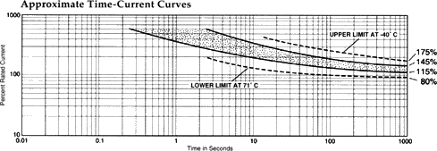
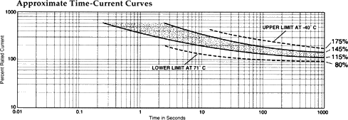
I'm attaching the time-current curves for a typical Klixon 7271
circuit
breaker. Per their specifications, the Klixon may never trip at
all with
a 10% to 45% overload. With a 35 Amp breaker, that would mean the
hydraulic pump could draw from 38.5 to 50.75 Amps without the breaker
ever tripping. At a minimum, your wiring needs to be able to handle
that. AWG #10 would be a minimum, I think. With a locked rotor and
assuming the pump draws somewhere around 70 Amps (a 200% overload with a
35A breaker), the Klixon 7271 circuit breaker would trip anywhere
between 8 and 80 seconds. It's my belief that either the pump itself or
the wiring would burn up if the breaker took 80 seconds to trip. Data
for other Klixon models can be found at:
http://www.sensata.com/download/klixon-circuit-breaker-aircraft-catalog.pdf
Now
looking at the Maxi-Fuse data at
http://www.littelfuse.com/data/en/Data_Sheets/299.pdf, I find that a 35
Amp Maxi-Fuse will open on a 200% overload between 6 and 40 seconds (20
seconds, on average), substantially faster than a similarly rated
circuit breaker. The 30 Amp Maxi-Fuse, if one chose to use that rating,
would open in less than ten seconds with a locked rotor.
The point
of all this is that we builders should have some idea what the
hydraulic
pump draws under what conditions, and the capabilities and
limitations of
whatever device we choose to protect it and the wiring.
One advantage to
using the Maxi-Fuse rather than the circuit breaker, is
that it allows the
builder to experiment and find the proper rating for
his installation
without having to rewire the panel.
*Addendum: In the link above, they
listed the cold resistance of the 40A
Maxi-Fuse as 1.42 milli-ohms. So I
installed one of those as a shunt and
re-did the test. I came up with
similar (even higher) numbers than
before: 211/126/54 Amps. I guess my
'gut feeling' was wrong. Now I'm
going to have to buy a 200A shunt to
verify all this. Nuts!

--
For archives
and unsub
http://mail.lancaironline.net:81/lists/lml/List.html

tripcurve-7270.gif
|
|