I believe both viewpoints of this
discussion/thread have elements of correctness.
If I understand it correctly, then the pictures
and discussion below are an attempt to add some clarity.
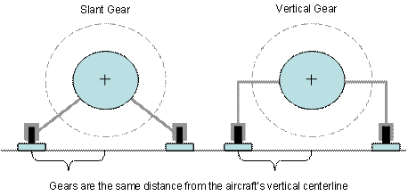
Imagine two identical airplanes except
they have different landing gear geometries – but they are the same and symmetrical
at the ground (and identical weights).
For definition let’s call the left
side the slant gear and let’s call the right side the vertical
gear

By definition: Torque = Moment Arm X Force
(perpendicular to the direction of rotation).
For all mention of “forces on the scales”
below, I am assuming the scales have been zero’d with the aircraft not
running (i.e. subtracting the tare weight of the aircraft).
So, lets get to work…
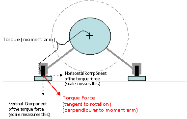
If you were attempting to measure torque
using the slant gear aircraft, and were using the actual gear geometry as the
basis for measuring the relevant forces and moment arm, then the scale would
only indicate a portion (the vertical component) of the torque force. (ref: slant
gear picture below). Note, the Moment Arm is the slant distance from the
axis of rotation to the contact spot on the scale

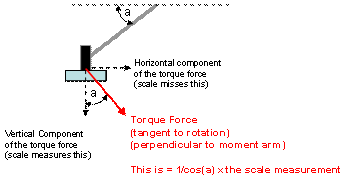
In this case, a geometric (trigonometry) correction
factor must be applied to the force indicated on the scale. The
correction factor is the 1/cos of the gear angle (measured from horizontal).
(Ref: diagram below)
Also note: the correct gear angle is to
the contact spot on the scale – not necessarily the leg itself.

Thus (in this case), the Torque = Moment
Arm X Force (on the scale) X 1/Cos(gear angle)
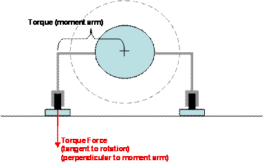
However, if you were to use the vertical gear
aircraft, the gear geometry is already perpendicular to the moment arm. Thus,
the scale would measure the complete (correct) force vector (no correction
factor needed).

Thus (in this case), the Torque = Moment
Arm X Force (on the scale).
In both cases the scales will read the
same. How can this be???
Note: the moment arm (as measured) is
shorter for the vertical gear aircraft. The “magic” is that
the slant gear correction factor (trigonometry for decomposing the vertical and
horizontal force components) is the same as the trigonometry that affects the
length of the respective moment arms. Thus, correction factor is “already
included” in the Moment Arm of the Vertical Gear scenario.
Of course the actual gear configuration doesn’t
really matter since “the scale doesn’t know”. So, if
you want to use the force measurement directly off the scale, you need to use
the horizontal distance from the centerline as the moment arm (similar to the vertical
gear example above). You can do this on any gear configuration.
Please comment on any corrections and/or
improvements to this attempted explanation.
Rick Titsworth
rtitsworth@mindspring.com