Pressure ratio boost creep.
Ok, here is what I find. The
absolute pressure ratio with boost is given by (Pa+Pb)/Pa where Pa is
ambient pressure (atmospheric) and Pb is the differential boost
pressure (what we normally see on a boost gauge).
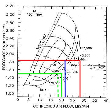
So lets take a nominal boost figure
of 7.5 psi. At sea level we have (14.7+7.5)/14.7 = 1.51. First
looking at where sea level take off would put john on the compressor
chart Eric provided. I believe John's take off rpm is around 4000
rpm. That would give a mass flow of approx 18 lbm/min. So that point
is plotted on the compressor map as the intersection of the dashed
green lines and the solid green. I also plotted his mass flow at 5000
rpm at sea level at 7.5 boost just so there would be a similar point of
comparison at altitude, that is the intersection of the two solid green
lines..
Now John was at 11,000 feet so
looking at altitude charts it looks like Pa at that altitude would be
about 9 psi. So if one was still maintaining a differential boost
gauge reading of 7.5 psi we would have (9+7.5)/9 = 1.83 pressure ratio.
I don't recall John's rpm but
I think it was 5000rpm. That would give a compressor mass flow of 27.3
lbm at sea level - that is the intersection of the two red lines -
However, that mass flow figured needs to be adjusted for less dense
air at 11000 feet that would bring it down to approx 22.7 lbm/min
flow. That is the intersection of the red and blue line.
As best I could eye ball it, that
shows the rotating assembly increased rpm by approx 12,000-15000 over
the sea level rpm just due to altitude pressure ratio creep along. The
turbo had to spin fast/work harder to maintain the 7.5 psi boost at
altitude due to the lower ambient pressure/density.
So clearly the effect of "altitude
creep" on pressure ratio (provide same boost level is maintained from
sea to altitude) is to cause the turbo to rotate faster. But, this
along does not appear to put it in a risk zone of overspeeding. Would
a BOV opening and possible adding to the rotation speed take it there -
don't know, can not show that it would or would not.
Do notice however that the rpm lines
of the turbo tend to curve very steeply downward toward the right part
of the graph. So it would not take much more mass flow to put John's
operating point over further to the right into that region where the
rpm increases very dramatically for very little additional mass flow.
If Eric's postulation that a BOV opening adds to the mass flow through
the compressor is correct then would the BOV opening under those
conditions be enough to push the turbo into a danger zone??
Don't know can show it would or
would not. But, this makes me lean more toward over speeding as a
possible source of John's turbo failures. IF this analysis is anywhere
close to portraying what may have happened, I would think it would
indicate that a waste gate is a lesser risk approach to boost control
for an aircraft installation
FWIW.
Ed
Ed Anderson
RV-6A N494BW Rotary Powered
Matthews, NC

 Homepage:  http://www.flyrotary.com/
 Archive:   http://lancaironline.net/lists/flyrotary/List.html