|
|
Hi Charlie, I sent my deposite to Mr. Musk but no joy on that Starlink dish yet. I guess Verizon finally realized there are a few people out here.
Not sure if i mentioned it or not (Alzheimer's knocking?) But I got the RV-8 flying again after that incident on take off a few years ago. The extended wings and 20B make it perfect for high altitude airports. Maybe Tracy will post again with more info, but my interpretation is that the inlet dia of his inlet 'pipe' remained the same, but instead of the simple 'pipe' pointing forward, he made a fat radius lip to fair the *outside* of the 'pipe' into the outer cowl shape. If mine doesn't cool with the stock James inlet rings (which are relatively sharp lipped), I'll just fair them out to the biggest radius I can manage in the space available. Frontal area won't change, so no loss there. He mentioned cooling improvements in climb; that seems likely to be caused by the inlet being basically an airfoil, and the sharp edge trips to turbulent flow at the inlet, while the 'fat' rounded lip acts like a fatter airfoil at high angle of attack in climb.
I gave up on 'optimum' while I was making my radiator & oil cooler diffusers. It just wasn't reasonable to expect optimum shapes given the space and fabrication constraints. I'll be elated with good enough.
Marc, The discussion isn't about the shape of the inlet; it's the shape of the 'lip' around the inlet. (Examples: stock RV cowls have really fat lips; the Sam James (round inlet) aftermarket cowls have sharper, thinner lips.) It's widely accepted that a circle is the optimum inlet because it has the best area to surface ratio, but hardly any of us have round heat exchangers, so going from round to rectangular makes it harder to maintain the perfect expansion rate in the diffuser (duct) and keep air flowing all the way to the corners of the HE.
As always, I could be wrong.
Charlie
Thanks Charlie. Got a pretty good grip
on that.
I was referring to Tracy's post on 4/28/2011:
" Finally got
around to finishing my cooling inlets. (pictures attached).
Up until now they were simply round pipes sticking out of
the cowl. The pipes are still there but they have properly
shaped bellmouths on them.The shape and contours were
derived from a NASA contractor report (NASA_CR3485) that you
can find via Google. Lots of math & formulas in it but
I just copied the best performing inlet picture of the
contour. Apparently there is an optimum radius for the
inner and outer lip of the inlet. There was no change
to the inlet diameters of 5.25" on water cooler and 4.75" on
oil cooler."
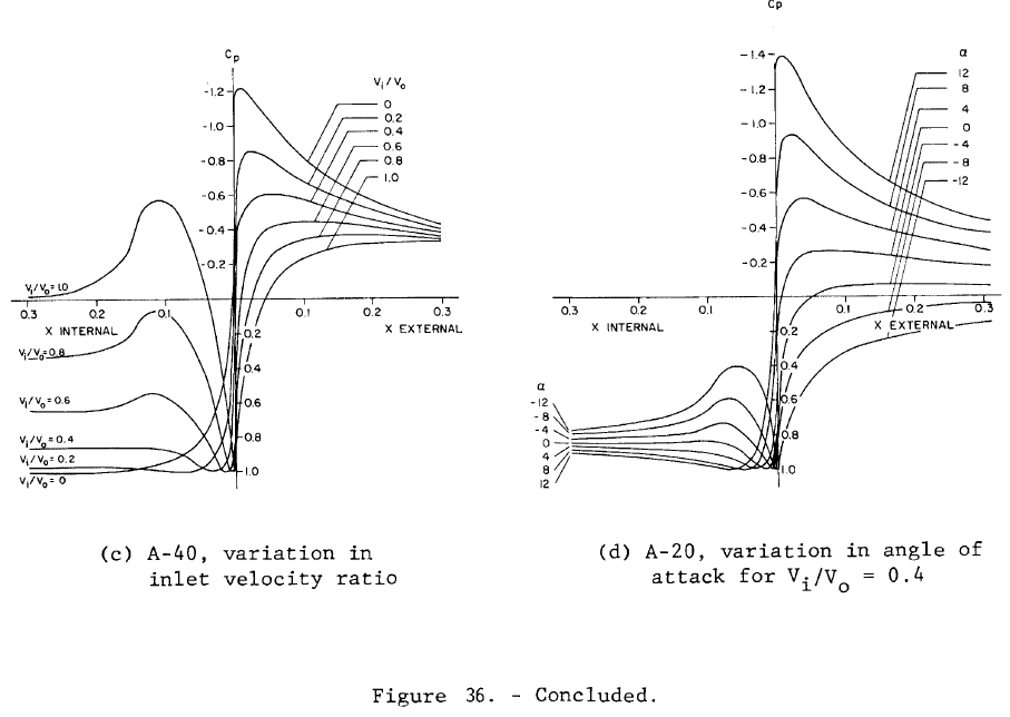
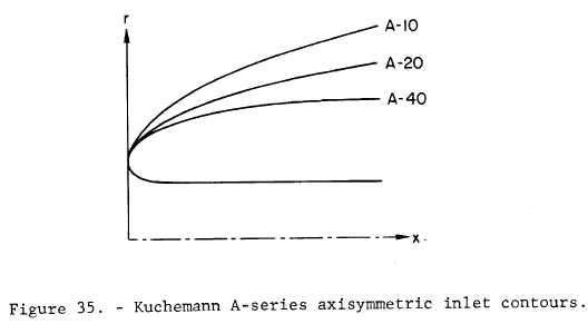
So, which inlet picture?
And where do you see the optimum radius?
I'm beginning to think that Tracy want's to keep it a secret!
First the wrong report number, then ... :)
Finn
On 7/3/2021 9:49 AM, Charlie England ceengland7@gmail.com wrote:
Hi Finn,
I was hoping
someone with better memory/understanding would jump in, but
I'll take a swing at 'general principles'.
If memory
serves, the guys who have applied the paper to hardware
recently have said something like this:
The sharper
edged lips are the most efficient shape where the flow is
'perfect' into the diffuser, and there's no spillage over the
outside of the lip. But in our typical situation we need lots
of flow at low airspeed (climb profile; high power) and less
flow (relative to freestream) at high airspeed (cruise). If
airspeed is high enough that some of the air in front of the
inlet can't get in and must divert around the lip, the sharp
edge of the lip will cause turbulence and drag on the outside
of the airframe (at high airspeed, where it hurts the most).
So, we can't truly optimize the lip. If a cowl flap will be
used to increase cooling flow at low airspeed and reduce it at
high airspeed, that means there will be significant spillage
around the lip at high airspeed. So while the fatter lip is
less efficient in the ideal flow situation, it ends up being
better in the real world, because we must be able to cool at
low speed and we want minimum drag at high speed.
There's also
the 'internal vs external diffusion' issue. I think Bernie
Kerr was the 1st person that talked to me about that. Internal
(K&W duct, for instance) is theoretically more efficient,
and could use a sharp edged lip, but it's really difficult for
us 'measure with a micrometer; cut with an ax' builders to get
perfect. So the safer thing is to go big on the inlet to
ensure plenty of flow, and then throttle the outlet to match
actual flow to conditions, with a cowl flap. Since we'll have
a lot of spillage around the inlet with the flap closed, that
means a fat lip on the inlet to minimize drag when there's
lots of spillage.
Or I could
have an advanced case of oldtimer's, and I'm remembering it
wrong.
I hope
someone will correct me if that's the case.
Charlie
Thanks. I guess I kept missing it because I don't
understand what I'm looking at.
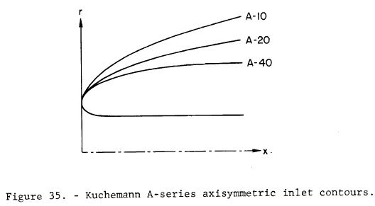
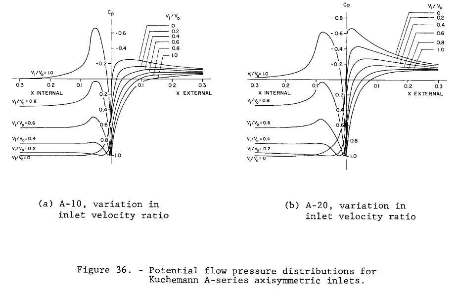
Can anyone help me understand the following and show me
the optimum inside/outside radius ratio (which I assume is
one of the A-10 to A-40 contours):
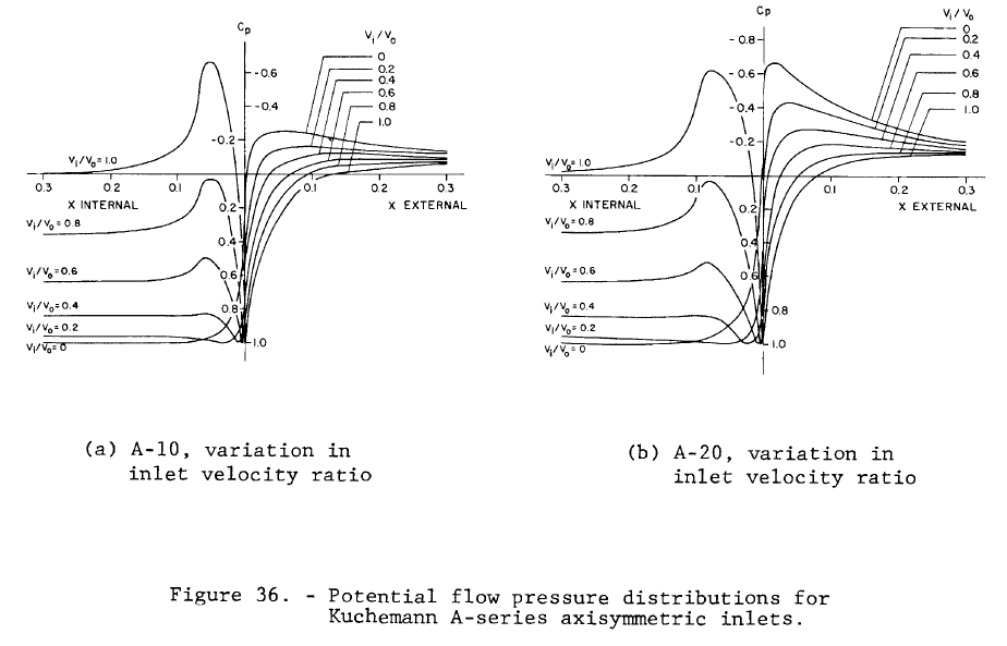
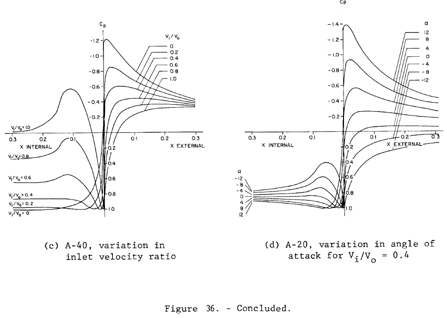
Finn
On 6/30/2021 9:45 PM, Charlie England ceengland7@gmail.com wrote:
Seems likely; I don't recall seeing a CR3485
referenced anywhere, either.
On 6/30/2021 4:42 PM, Finn Lassen finn.lassen@verizon.net
wrote:
I tried in vain to find NASA_CR3485 (well, I
found a NASA contractors report on animal
studies).
I wonder of he meant 3405?
Anyone found a better match?
Finn
On 4/28/2011 9:07 AM, Tracy wrote:
Finally got around to
finishing my cooling inlets. (pictures
attached)� Up until now they were simply round
pipes sticking out of the cowl.�� The pipes
are still there but they have properly shaped
bellmouths on them.�� The shape and contours
were derived from a NASA contractor report
(NASA_CR3485) that you can find via Google.�
Lots of math & formulas in it but I just
copied the best performing inlet picture of the
contour.�� Apparently there is an optimum
radius for the inner and outer lip of the
inlet.�� There was no change to the inlet
diameters of 5.25" on water cooler and 4.75" on
oil cooler.
The simple pipes performed adequately in level
flight at moderate cruise settings even on hot
days but oil temps would quickly hit redline at
high power level flight and in climb.�
The significant change with the new inlet shape
is that they appear to capture off-axis air
flow� (like in climb and swirling flow�
induced by prop at high power)� MUCH better
than the simple pipes. �� First flight test
was on a 94 deg. F day and I could not get the
oil temp above 200 degrees in a max power climb.
�� They may have gone higher if the air
temperature remained constant but at 3500 fpm
the rapidly decreasing OAT kept the temps well
under redline (210 deg F).
I have an air pressure instrument reading the
pressure in front of the oil cooler and was
amazed at the pressure recovered from the prop
wash.� At 130 MPH the pressure would almost
double when the throttle was advanced to WOT.
� That did not happen nearly as much with the
simple pipes.��
These inlets ROCK!
Tracy Crook
nadfchpfafimnegl.png
kbdejbnihmgdehea.png
bnmfmdnlndmefidc.png
|
|