The point of my previous message was that one can be well assured that the engine side of the cooling system is working properly if a coolant delta T of about 15 degrees is seen at full throttle at sea level. This can
be done on the ground and should take only a minute or two. The inlet and outlet coolant temperatures will both rise so the test would need to be terminated before damaging anything.
If the expected coolant delta T is observed, then one could confidently concentrate the effort on sizing the radiator core, obtaining a reasonable mass air flow through the core, or both.
At sea level with a 16.5 sq in radiator air inlet, air temperature rise of 120 deg F (from 80 to 200 deg), 9 gal/hr fuel flow, 115,000 BTU/gal fuel, and 27% of the heat from the fuel going into the cooling system, this
would require 200 MPH air velocity through the inlet to control the temperatures. If one third of the heat was rejected through the oil (I've measured closer to from 10 to 15%) the radiator air inlet velocity would still need to be over 130 MPH. These velocity
estimates are conservative.
It might be useful to install a pitot-static sensor in your radiator air inlet to measure the actual air velocity.
I suspect you are trying to do the impossible, but it wouldn't be the first time I've been wrong.
Steve Boese
Hi Guys
In search of cooler running this is what we did today and plan to do next.
Any insights/thoughts welcome.
Today we:
1. Installed a new pressurised tank with 21psi cap at the highest point possible. It is fed from:
A. Rear Iron.
B. Top of the coolant out manifold (engine heading for radiator).
C. Top of radiator inlet tank
It returns to the pump inlet via a hose with a 1/8” restriction.
It overflows into an expansion tank accessible via a hatch in the top cowl
2. Tested new config:
A. I wondered why she wasn’t running as sweet as usual and realised the Leading plugs weren’t firing so fixed the problem.
With an OAT of ~ 80F after 20 mins of idle at 1800 rpm water gets to over 225 and I shut it down. (No significant change from last setup)
B. Measured Cowl pressure at a point between water radiator and cowl flap referenced to Static -
At idle the pressure is 0 inches of water
At 6000rpm (fine pitch) it hits about negative 1/2 inch of water (the exit shape, exhaust augmenter and cowl flap appear to be producing some negative pressure in the cowl)
I’ve currently stuffed the gear opening full of pillows and rags to emulate the gear being up and door closed.
So here is the detail:
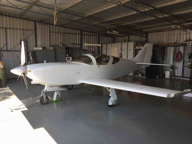
The 193 inch^3 oil cooler is fed by a 7.4 inch^2 inlet well below the spinner and into a trumpet diffuser.
The 540 inch^3 water cooler is fed by the 16.5 inch^2 right cheek inlet very close to the spinner and into a trumpet and then wedge diffuser. (Tried to copy Tracy’s RV8 cooler design)
Ive put a matrix of wool tufts over the back of the water cooler and distribution appears quite even.
See photo showing oil cooler inlet below spinner vs cheeks.
Currently the oil temps lag the water temps by a good 30F.
So next opportunity I’m thinking:
1. Because its a quick and easy test, I’m planning to close off part of the oil cooler inlet and see what this does to the water temps.
Will this provide a better balance between oil and water with the water rad getting a better share of the exit air flow?
2. Seek to plot a set of pressure measurements at various locations around the cowl and diffusers for various;
1. RPM’s
2. Cowl Flap position
3. Gear door open / closed (stuffed full of pillow and rag).
Many thanks for your ponderings and any of your thoughts.
Cheers
Steve
Perth Western Australia
Glasair Super IIRG - Renesis 4 port RD1C EC3 EM3
On 28 Dec 2017, at 7:37 am, Stephen Izett
stephen.izett@gmail.com <flyrotary@lancaironline.net> wrote:
Hi Steve
Aeroplane has not flown. We are still testing on the ground in OAT’s of 80-100F
At idle (1900rpm) Delta T’s across Oil coiler - 18F, Water coiler - 8F
We are seeking to do two things:
1. Review our design - have we made a clear mistake somewhere -
a. We managed to not have an air bleed at the engine coolant in/out which is the highest point!
We only have returns to the pressurised expansion tank/cap from rear iron and one from the top of the radiator in tank (returning to pump in).
b. We do not have a small hole in the Renesis bypass which we plugged.
c. Lynn uses a restrictor in the outlet to make sure the pump isn’t cavitating. Our coolant out plumbing has far less restriction than the stock setup (All be it the radiator is a dual pass so presents significantly more resistance)
d. We have just finished building a cowl flap in an attempt to control cowl pressure.
2. Do the science and seek to measure what the air and water are doing.
a. Not sure how to measure the water flow easily.
b. We are testing today to see what air pressures exist around the diffusers and cowl.
Cheers
Steve
On 28 Dec 2017, at 3:00 am, Steven W. Boese
SBoese@uwyo.edu <flyrotary@lancaironline.net> wrote:
Simply determining radiator coolant delta T may be useful in troubleshooting the cooling system. The water cooling system is a closed system with two heat exchangers: one is the engine putting heat into the coolant and the other is the radiator removing heat
from the coolant. When all of the coolant flows through the engine and radiator (coolant bypass passage blocked by either a plug or a fully open thermostat) the engine and radiator must have the same coolant delta T. At a given power level and coolant flow
rate we all should see similar delta T's since we are using very similar engines. At sea level full throttle, that coolant delta T should be close to 15 degrees F. Since the heat exchanger characteristics of a clean engine are essentially fixed, a coolant
delta T of much more than15 degrees F at full throttle would most likely be a result of insufficient coolant flow rate through the system. This could result from a defective water pump or too much coolant bypassing the radiator such as due to an incompletely
closed thermostat bypass passage, too large air bleeds from engine coolant high points, or an open cabin heater coolant loop. An EWP would introduce an additional variable.
With proper coolant flow rate, when the radiator cannot remove enough heat from the system, the overall coolant temperature will rise until one of two conditions are achieved. First, the radiator may be capable of removing enough heat with a greater delta
T between the coolant and the air. The system will stabilize, but the delta T's of the coolant across the engine and across the radiator will remain essentially equal and unchanged. This type of behavior is demonstrated in the attached data plot for a full
throttle climb from 7,000 to 14,0000 ft msl with a typical OAT decrease.
The second condition would be to boil the coolant and remove heat due to the phase change. This may not maintain a closed system and the stable condition would then, of course, be temporary.
The goal of designing the radiator side of the cooling system is to size the radiator and air flow through its core to achieve the desired overall coolant temperature. Trying to change the coolant delta T at a given RPM and power level will prove frustrating.
The same would be true of the oil cooling system if the oil flow rate was consistent between our systems. However, if part of the oil flow is returned to the sump at the front cover relief valve, comparisons between different setups will be of limited value
unless the actual oil flow rates through the oil coolers are known.
Steve Boese
RV6A, 1986 13B NA, RD1A, EC2
<coolant delta T.jpg>--
Homepage: http://www.flyrotary.com/
Archive and UnSub:
http://mail.lancaironline.net:81/lists/flyrotary/List.html
--
Homepage: http://www.flyrotary.com/
Archive and UnSub:
http://mail.lancaironline.net:81/lists/flyrotary/List.html