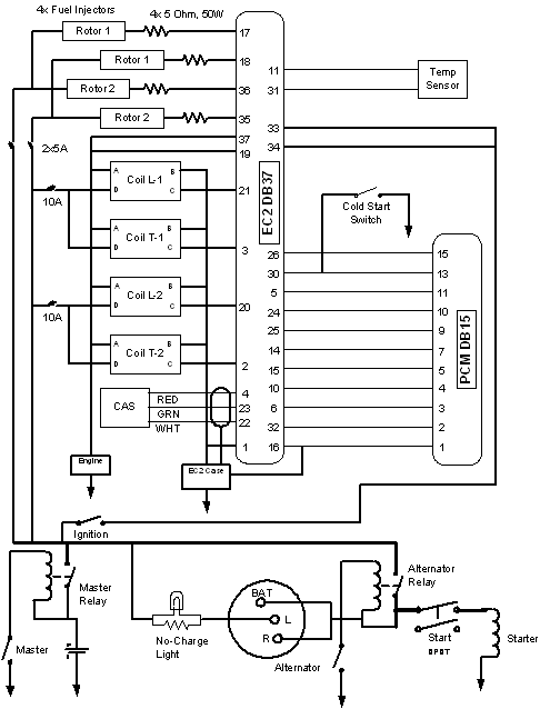
I did similar to Steve, used 2 switchable fuses (5A) for the Injectors (1 PRI and 2 SEC) with a separate cold-start switch as it was already there … I wanted/have to control it manually.
I also used 2 separate switchable fuses (10A) for the ignition coils (1 ROT1 and 2 ROT2) … my schematic of ignition and Main Electrical is below.
Jeff

From: Rotary motors in aircraft <flyrotary@lancaironline.net> on behalf of Charlie England <flyrotary@lancaironline.net>
Sent: Thursday, July 17, 2014 12:14 PM
To: Rotary motors in aircraft
Subject: [FlyRotary] power circuit design, was: actual current use by a rotary?
Charlie,
I chose to install switch type circuit breakers, one for the primary injectors and one for the secondary injectors. I did this because if one injector fails, the backup
function requires the corresponding injector of the other rotor to be shut off and then the cold function to be activated. If there were a power draw that tripped the breaker, the result would already take care of that first step. The down side is that the
cold switch needs to be used for the backup function instead of being taken care of by the second pole of the recommended DPDT injector switch. This required no additional space on the panel.
I did the same thing for the leading and trailing coils but for testing purposes rather than risk mitigation.
Steve Boese
RV6A, 1986 13B NA, RD1A, EC2
Well, time for some followup.
My 1st draft for circuit protection looked a lot like what Steve describes (thanks, Steve), with individual fuses for virtually everything, including an individual fuse for each injector and each ignition coil. After ruminating over the actual loads for the
injectors & coils, I'm having second thoughts. The GM coil harness I have in hand has a single DC power wire for all four coils that it feeds (obviously isn't a part intended for flight, but included in Tracy's installation manual).
The obvious concern is whether an individual coil or injector failure has a statistically significant risk of taking out the power supply that's fused for the total load. If there's no statistically significant danger, weight & complexity could be reduced by
feeding the coils and injectors as groups.
So, is there any consensus on how to handle injector & coil wiring? IIRC, there have been some coil failures in flight; were those planes wired with a single fuse/breaker protecting all the coils, or with individual fuses/breakers for each coil? What about
the injectors?
Any failure modes I'm missing? (other than a dead short on a supply wire, of course)
Thanks,
Charlie
This message, and the documents attached hereto, is intended only for the addressee and may contain privileged or confidential information. Any unauthorized disclosure is strictly prohibited. If you have received this message in error, please notify us immediately
so that we may correct our internal records. Please then delete the original message. Thank you.