Hi Folks;
Here are some notes/pics on how to construct the adjustable length intake.
Hopefully this will lead to a few more data points...
Darn, too big, try again.
Cheers
Cary
TromboneIntakeConstructionv0dot3
Peripheral Port, Slide throttle, Telescopic (trombone) Intake Construction, draft 0.3
Here are some quickie construction notes and comments to build your own trombone intake for the 13B.
This particular design uses the intake tubes themselves as both the guide and the sealing surfaces – not the most robust design, but simple and, I hope, effective.
This design is probably not well suited to car applications with rapid acceleration requirements and high duty cycles requiring dynamic adjustment to the tuned length. This design is better suited to a high rpm, low duty cycle aircraft application with fixed or fewer length adjustments. This particular setup should be useful to at least identify the tuned lengths for the intake system using some sort of a wide-band or low-band O2 sensor.
For a more dynamic throttle response, an intake using a Mazda style intake with linear bearing or Teflon bushings is probably better suited.
The addition of a plenum, with such an upstream fuel injector setup, should be considered mandatory, in order to avoid a spectacular fireball as the perfect 40psi fuel cones impact the ridiculously hot Wankel exhaust ;)
Bill of Materials – excellent service from these guys.
Velocity Stacks (air intake bellmouth)
http://www.velocity-of-sound.com/ - 2x48-70 velocity stacks, very nice – thanks Patrick
Precision drawn 6063-T832 drawn aluminum tubing
(drawn or double drawn aluminum tubing is exceptionally dimensionally accurate)
http://www.texastowers.com/aluminum.htm
6’ x 2.000 OD, 0.058 wall
6’ x 2.125 OD, 0.058 wall
I only used 9" for the intake itself, the remainder was used for alignment purposes, shipping is reasonable via UPS under 6’ length. It also leaves additional material for a redo…
180 degree 6061 2.125 OD Ubend to be cut for 2 x 90 bends:
http://www.burnsstainless.com/AluminumTube/Ubends6061/ubends6061.html
1/4" inch threaded rod, 36"x2, lock washers, nuts
6061T6511 extruded aluminum sheet stock, 1/8" inch thick, 4" width for sheet metal slide and trombone frame flanges
silicone grease
Required Equipment
Basic milling machine
Holesaw
Boring head arbour
Aluminum Brazing/welding setup
Additional Info
For slide throttles, take a look at:
http://www.rotaryeng.net/
For information on building Peripheral port housings:
http://www.rotaryeng.net/
http://www.rx7club.com/showthread.php?t=144200&page=1&pp=15
http://lancaironline.net/lists/flyrotary/List.html
Random Ramblings
The slide throttle is flush with keg. The notch in the throttle was to avoid the stock water pump, I wish I had been annoyed enough to chop it up earlier...
Same for the adjustable, telescopic intake. I will rebuild almost flush with the engine and at a different angle flush with the bottom of the oil pan after testing.
The intake also needs to be supported at another point. I noted that someone had already pranged the prototype sitting in our chapter hanger before Oshkosh.
Doublers on some of the (in my case HTS-2000 brazed) joints would not hurt either.
Usable range (from rotor face) is 19-27". Length of the straight section is 9". This should put tuned length range somewhere between 5250 and 7500 based on the Mazda papers and rough calculations.
The setup could be modified for inflight/dynamic adjustment with a throttle type cable/wheel.
Injector location will probably make it difficult to pull fuel uphill for start - we will see.
Based on Francois' (Mistral) comments I will probably move the injectors closer to the keg, Besides, they are mucking up the airflow and the threaded rod and fuel injectors also add a lot of mass quite far out for such a light intake.
It would require support in any vehicle.
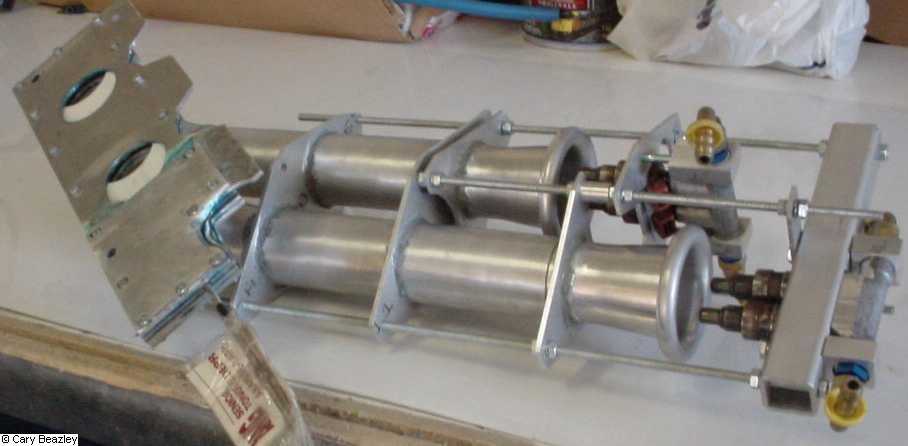
I am really unsure what is best. The question always arises as to whether laminar or turbulent is better. I built the prototype with smooth airflow as the intent. The better economy of the way forward fuel injectors certainly promises latency/bogging for rapid throttle changes and possibly icing and fuel droplet coalescence on the walls and dripping. I figured I would try this on the teststand and rebuild later anyway. The intake (intentionally) has a lot of roughness prior to the 90 degree bend. Hopefully ram air and throttle opening (see Picture 5 - Slide throttle part open below) will help force air into the engine, as a minimum this intake is better than those sticking out into the freestream velocity at 90 degrees.
One of the objectives was to reduce the frontal area of the Wankel installation to take advantage of the potentially smaller profile, this could be further reduced.
The trombones slide easily enough, requiring a few ounces of pressure going down, a bit more (a better guess 3-4lbs) sliding up (mostly due to FI/rod setup)
Actual Construction
It took some head scratching and tricks to get everything to line up well enough.
I wasn't sure if it could be realistically done - the next test is at temp with airflow.
I am also unsure of the stability of the Teflon slide at higher temps, another alternative would be Kelvin? or a Teflon coated, anodized, aluminum plate.
One of (many) concerns with this offset runner was to build the adjustable runners stiff enough to move together and flexible enough to compensate for any slight misalignment.
The main tricks in order to get near perfect alignment on the throttle plate tubes were tight tolerances on match drilled holes for the flanges and long tube inserts to help align things before fixing them.
Steps
Weld/braze the velocity stacks (trombones) to the take 9" intake runners

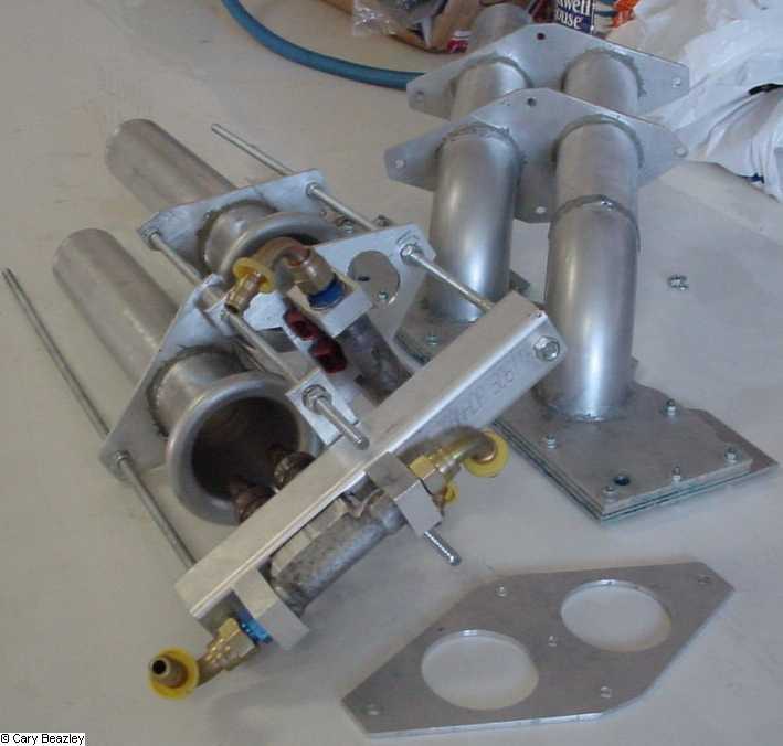
Picture 1 - the pieces – 3 dual runners flanges and 3 portions of flanges (sorry, already mostly assembled in the photo)
Cut and drill the holes for all of the 3 larger dual throttle runner flanges (bottom central right) and 3 detachable trombone flanges at the same time to try and ensure match drilling accuracy. The runner holes were cut with a hole saw an finished with a boring head arbour slightly undersize. The holes for one runner should be very tight/difficult to slide on to act as a reference. The other should be (slightly) less tight to allow some movement for fitting and alignment to the throttle plate.
Two (2) of the three (3) matched drilled flanges are used to line up the runners to the throttle plate (below).
The flat section on the bottom of the flanges is intended for a long flat, even surface. The 4 outer holes of the flange were used for alignment guides with the .25 inch threaded rod and nuts to hold the flanges and tubes in position while they were permanently fixed (weld/braze/whatever) as measured by micrometer. The throttle attach plate was also fixed next.

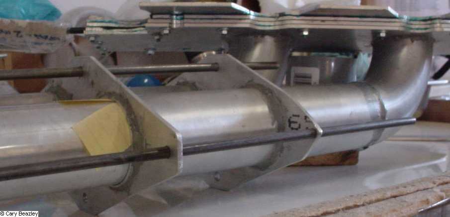
Picture 2 - Tube alignment at the throttle end
The triangular cuts on the rightmost flange were to avoid my test exhaust setup.
The yellow paper (above and below) is a re-creation of the 0.0035-0.004 paper shims that were used to help. These were used on every inserted joint.
Align the throttle plate intake runners with the help of the flanges, threaded rod of the remaining 5’ of tubing . I moved the far end flange back and forth several times to try to ensure I was dead center (yes, there is still movement at 5’, the farther you insert the tubes the less the movement). The goal was to near perfectly align the throttle plate runners and have the trombones "float" together in a frame that was just stiff enough to move them in unison and loose enough to "float" and compensate for minor misalignment.

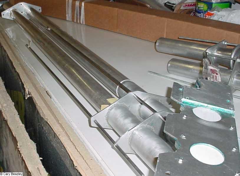
Picture 3 - Full length alignment
Note the gap in the top tube near the flange, this was a short section of tubing cut to join the remainder of both the 2.125 and 2.000 tubing so they could be used for alignment. There is a similar gap and section of tube inside the flange at the far end. These also had paper shims.
NOTE: it is very important that all tubes that are to inserted/slide be greased or they will scratch (guess how I found out?) The tube edge corners should also be rounded to reduce the possibility of "catching" or jamming.

Picture 4 - tube-in-tube
Once the throttle plate runners are secured, the adjustable trombones and smaller flanges can be inserted into the throttle plate runners, fixed using the threaded rod and permanently brazed/welded in position.
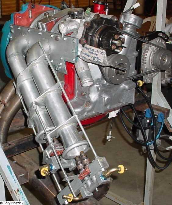
With the upstream injector placement, I added square aluminum tube to stabilize the frame and hold the injectors.
This prototype setup is ugly but should work well enough for a teststand or dyno…

Picture 5 - Slide throttle part open
INTAKE MOUNTED ON THE ENGINE

Picture 6 - Trombone minimum length

Picture 7 - Trombone extended
Some engine build specifics
- rebuilt 86 NA in excellent condition
- Teflon encapsulated orings
- rotary aviation apex seals
- race cleared 9.4 NA rotors
- ‘loose’ engine
- 3rd gen oil pressure reg, shimmed oil pressure control valve spring for higher pressure.
- modified oil/water cooling passages
- 2" Peripheral port modeled after the Lemans engine, slightly later open/close (why? Because Mazda has more dyno time than I do) and I have a pretty good map to follow.
- Peripheral port is an interference press fit of a conical (larger at the outside of the housing) sleeve insert into a conical hole straight through with JB Weld on the sleeve. Water passages filled with JB weld. The sleeve, cut into slightly and , effectively filled the gap between the tension bolts.
- Peripheral port passages were cut with a trued hole saw and faced with boring head on a basic milling machine
- Engine should be good for occasional forays into the 8500rpm range – output should be ~10-15% less than the Mazda Lemans curves.
- Final pictures show a chopped up water pump, this greatly facilitated installation and a smaller profile
- Pineapple racing alternator relocation bracket.
- Racing beat under drive pulleys
- Stock coils (possibly COP later)
- Megasquirt EFI
Expected Results
210-220HP @6000 rpm with a decently match tuned exhaust.
I'm guessing something like 275hp at 7500rpm.
~10-15% less than the Mazda curves at other rpms plus benefits of RAM effect
Paul Lamar’s Mazda Lemans 787 benchmark achieved the 240 HP at 6000rpm
Ceramic components seem to be worth about ~10% HP as a result of reduced drag/wear.
3rd spark plug -~2%
this engine has minor chrome corner seal wear/flaking, end housing wear about .001
reused some seals, not all measurements near minimum limits
rotary aviation seals apparently take longer to break in
exhaust splitters are in - I wanted the 7or 8db noise reduction and probably longer exhaust (probably worth 5-10hp?)
Madza has more dyno time!
Megasquirt Fuel Injection with O2 sensor feedback
The intakes and exhaust could benefit from tighter bend radii, this would probably entail a non-circular holes making custom fitting more difficult without basic shop equipment or more weld fitting.
Some regrets
I would do everything differently…
Ceramic $eal$
3rd Gen housings (which I now have)
All new seals
Could not find readily available larger diameter drawn AL tubing
Not chopping up the stock water pump earlier, this necessitated a lot of custom fitting (the notch in the slide throttle) for the slide throttle and intake.
Future projects
- Get the damned thing running first…bonehead!
- Possibly move some/all of the FI setup closer to the slide throttle
- combined Pport and side port intake for higher BMEP at lower RPM
- test E85/alcohol
- acetone additive in fuel?
- modified flame front channels in the rotor faces
Combination sideport/Pport intake
The premise is to have a staged Pport slide throttle combination along Paul's design for wide open throttle operation; and
a separate runner/butterfly for low speed/power operation using the center iron side ports/injectors.
The plan was to have a single, small diameter (say 1") intake runner supply air to the center iron intakes and fuel by the stock center iron injectors. I can't remember the intake velocity calculations but a smaller diameter could be tailored to provide velocities for a stable idle and lower power operation (with higher BMEP according to Kenichi Yamamto's? book). Staging of the PPort could take place around 3000rpm or so.
I am sure running on the center irons alone is not quite as good - how much?
With a single runner, an idle air controller would be an easy addition.
Cheers
Cary Beazley
thepieces.jpg
alignmentthrottleend.jpg
full-length-alignment.jpg

tube-in-tube.jpg
slidethrottlepartopen.jpg
trombone-minimum-length.jpg
|